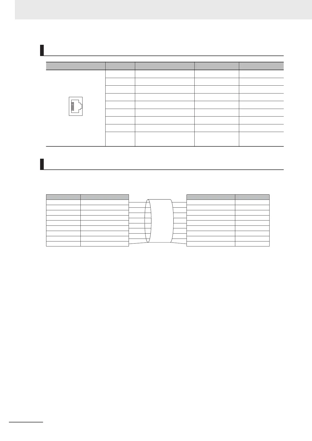
Pin Layout
Pin assignment Pin No. Signal name Abbr. Signal direction
1 Transmission data + TD + Output
2 Transmission data - TD - Output
3 Reception data + RD + Input
4 Not used NC -
5 Not used NC -
6 Reception data - RD - Input
7 Not used NC -
8 Not used NC -
Connector
hood
Security ground FG -
Wring
• Connect both ends of the cable shield to the connector hood.
•
Apply the T568A method below.
Pin No.
1
2
3
4
5
6
7
8
Connector hood
Pin No.
1
2
3
4
5
6
7
8
Connector hood
Wire color
White·Green
Green
White·Orange
Blue
White·Blue
Orange
White·Brown
Brown
Shielded cable
Wire color
White·Green
Green
White·Orange
Blue
White·Blue
Orange
White·Brown
Brown
Shielded cable
6 I/O Interface
6-12
FH Series Vision System Hardware Setup Manual for 3D Robot Vision (Z436-E1)

 Loading...


