5-5-2
Installation of 3D Vision Sensor
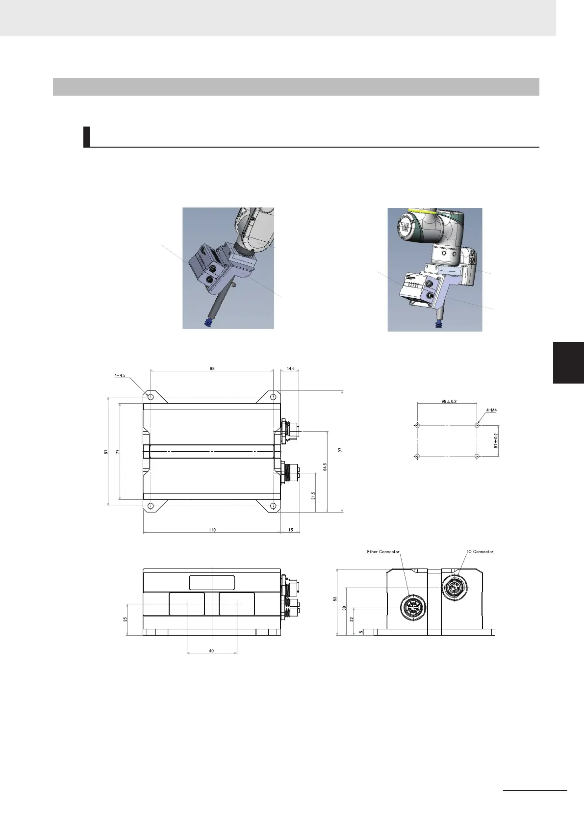
Mounting
Attach the camera to the 6th axis of the 6-axis articulated robot using a jig.
Securely secure the camera in four places using M4 screws. (T
ightening torque: 1.2 N•m)
• Example:
3D vision sensor
FH-SMDA-GS050B
Bracket
6th axis
3D vision sensor
FH-SMDA-GS050B
Bracket
6th axis
• Mounting dimensions(Unit: mm)
Mounting screw holes
Optical Axis
Optical Axis
dia.
5 Setup and Wiring
5-11
FH Series Vision System Hardware Setup Manual for 3D Robot Vision (Z436-E1)
5-5 Camera Installation
5
5-5-2 Installation of 3D Vision Sensor

 Loading...


