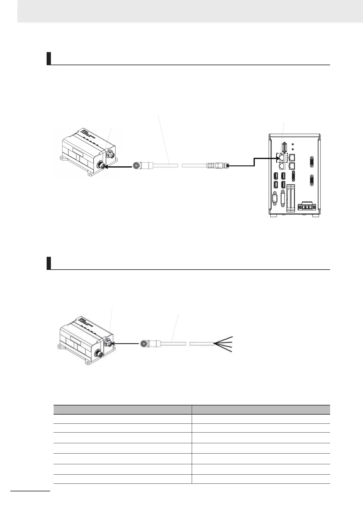
Connecting
Connect the camera cable (Ethernet cable FHV-VNBX / FHV-VNLBX: sold separately) to the Ethernet
connector on the 3D vision sensor
. Then connect it to the top of the two Ethernet connectors on the
sensor controller.
Ethernet connector
Ethernet cable
FHV-VNBX / FHV-VNLBX
Ethernet connector
3D vision sensor
FH-SMDA-GS050B
Sensor Controller
FH-5050
Wiring
Wire the signal line of the camera I/O cable (FH-VSDX-BX / FH-VSDX-LBX: sold separately) with a
crimp terminal. Insulate unnecessary signal lines and avoid contact with other signal lines.
Camera I/O cable
FH-VSDX-BX / FH-VSDX-LBX
3D vision sensor
FH-SMDA-GS050B
I/O cable connector
Wire color of camera I/O cable
Signal name Wire color
24VDC (For camera power supply) Brown
0V (For camera power supply) Blue
Unused
*1
Yellow
Unused
*1
Black
Unused
*1
Red
Unused
*1
Orange
NC Gray
5 Setup and Wiring
5-12
FH Series Vision System Hardware Setup Manual for 3D Robot Vision (Z436-E1)

 Loading...


