Precautions for Correct Use
• This camera cannot be used as a measuring instrument, because it is not an absolute dis-
tance. Use in combination with robot calibration.
•
If there are slight unevennesses, it cannot be recognized. There must consist of a surface of
20 x 20 mm or more
• The minimum recognition workpiece thickness is 5 mm or more.
• If the surface is strongly glossy and the reflection is strong, it cannot be recognized.
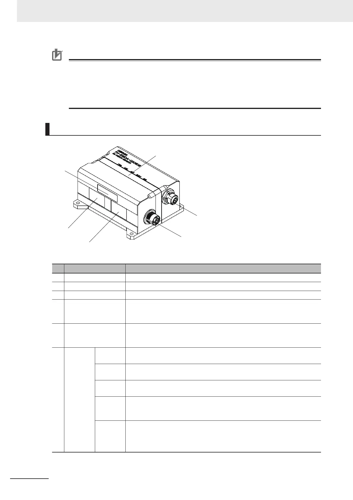
Component Names and Functions
Name Description
1 2D lighting unit Lighting for 2D measurement is arranged to illuminate the light.
2 3D lighting unit Pattern lighting for 3D measurement is arranged to illuminate the light.
3 Imaging unit Captures images.
4 Connector for camera
I/O cable
Use this connector when connecting the camera with a power supply using a
camera I/O cable.
Dedicated camera I/O cable: FH-VSDX-BX / FH-VSDX-LBX)
5 Connector for camera
cable (Ethernet cable)
Use this connector when connecting the camera with a FH sensor controller us-
ing an camera cable (Ethernet cable).
Dedicated camera cable (Ethernet cable): FHV
-VNBX / FHV-VNLBX)
6 Operation
indicator
PWR
(Green)
Lights while power is supplied.
LINK
(Green)
Lights when connected with Ethernet equipment.
ACT (Yel-
low)
Blinks while communicating with an Ethernet device.
WARM
UP (Y
el-
low)
Lights from startup to completion of warming up. Turns off after warming up.
ERR
(Red)
Lights when an error occurs.
For the error (system error), refer to the Camera Image Input AOS in the V
ision
System FH series Processing Item Function Reference Manual for 3D Robot
Vision (Cat. No. Z445).
3 Configuration
3-10
FH Series Vision System Hardware Setup Manual for 3D Robot Vision (Z436-E1)

 Loading...


