Command Control
232
FQ2-S/CH User’s Manual
for Communications Settings
Response (Vision Sensor to PLC)
Acquire Execution Mode
Acquires the FQ2 execution status (execution mode).
Command (PLC to Vision Sensor)
Response (Vision Sensor to PLC)
* The execution mode is classified into the following modes depending on the FQ2 execution status.
• Run mode: The mode to run actual measurements. I/O is possible with external devices such as a PLC.
• Stop mode: This mode is for monitoring/controlling the output status of the parallel signals through communication commands only.
Therefore, I/O that is unrelated to parallel terminal control is not possible.
• Input: Parallel signal input is not possible. Command input is not possible. (However, the terminal status monitor, set-
ting commands can be used)
• Output: Parallel signal output is possible. Data output is not possible.
• Adjust mode: The status where Touch Finder is connected and the Setup display is displayed.
This mode is for configuring settings and making adjustments, so measurement processing, I/O signals from external
devices, and command input are not possible.
• IO monitor setup mode: The status where Touch Finder is connected and the IO monitor in the Setup display is displayed.
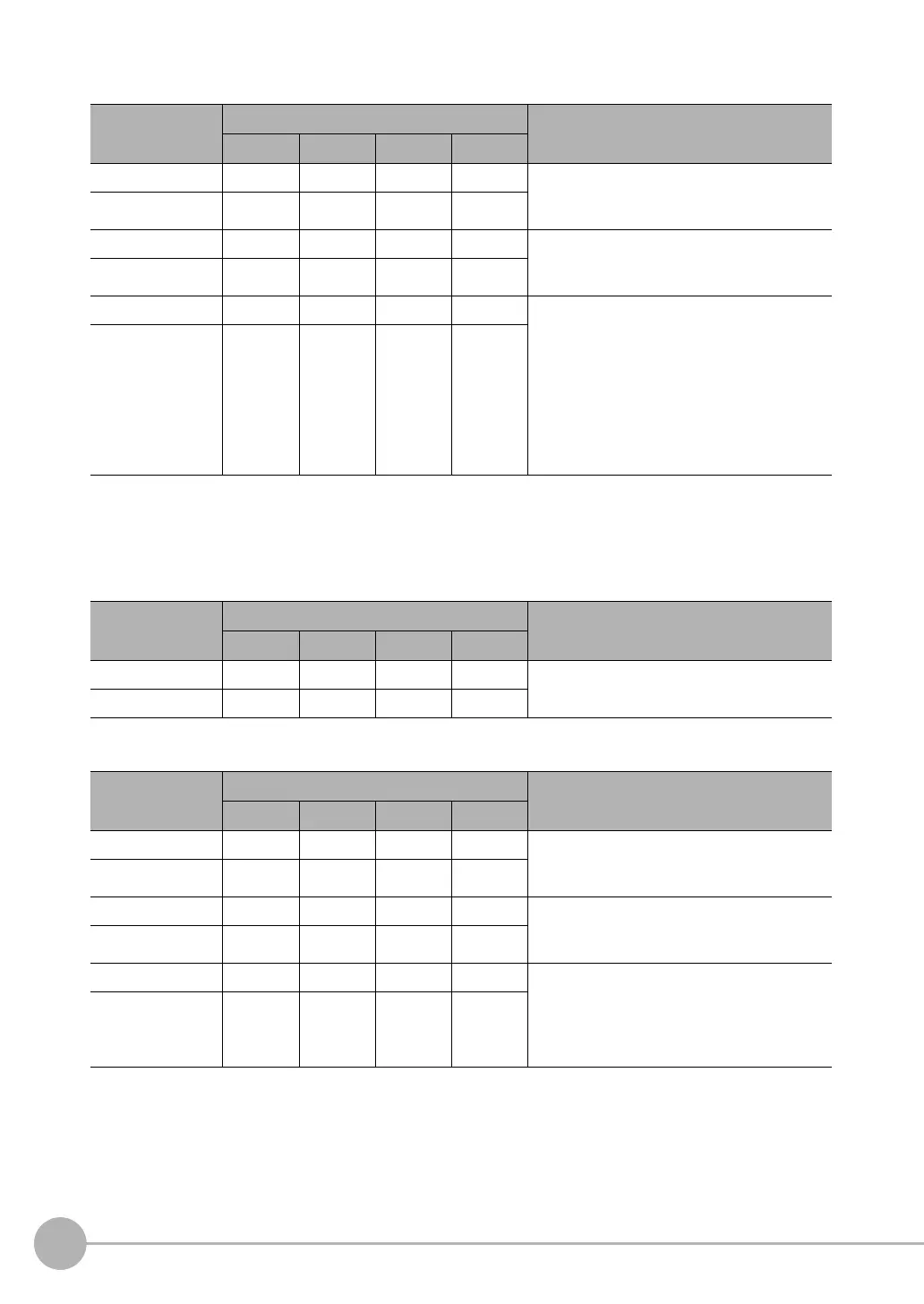
First word of
response area
Bits Description
12 to 15 8 to 11 4 to 7 0 to 3
+2 1000 0000 0011 0000 Command code
The command code for which the response
applies is stored.
+3 0000 0000 0010 0000
+4 0000 0000 0000 0000 Response code
Command execution result
0: OK, FFFFFFFF: NG
+5 0000 0000 0000 0000
+6 0000 0000 0000 0000 Terminal status (ON: 1, OFF: 0)
BIT0: IN0
BIT1: IN1
BIT2: IN2
BIT3: IN3
BIT4: IN4
BIT5: IN5
BIT6: IN6
BIT7: IN7
+7 0000 0000 0000 0000
First word of com-
mand area
Bits Description
12 to 15 8 to 11 4 to 7 0 to 3
+2 1111 0000 0000 0000 Command code
+3 0000 0000 0010 0000
First word of
response area
Bits Description
12 to 15 8 to 11 4 to 7 0 to 3
+2 1111 0000 0000 0000 Command code
The command code for which the response
applies is stored.
+3 0000 0000 0010 0000
+4 0000 0000 0000 0000 Response code
Command execution result
0: OK, FFFFFFFF: NG
+5 0000 0000 0000 0000
+6 0000 0000 0000 0000 Execution mode
*
1: Run mode
2: Stop mode
10: Adjust mode
11: IO monitor setup mode
+7 0000 0000 0000 0000
FQ2-S_CH_comm.book 232 ページ 2014年6月26日 木曜日 午前11時47分

 Loading...


