60 LD Cart Transporter User's Manual 14766-000 Rev H
3.5 Installing the Cart Brake Release
Callout Description Callout Description
A Route brake-release cable up to
brake lever
C Secure brake-release cable to
saddle tie
B 6 mm diameter (0.25 in.) hole
through rear tube wall
After the brake-release lever has been mounted on the cart payload:
1.
Push the free end of the lever cable through the hole in the cart’s upper-rear horizontal
tube.
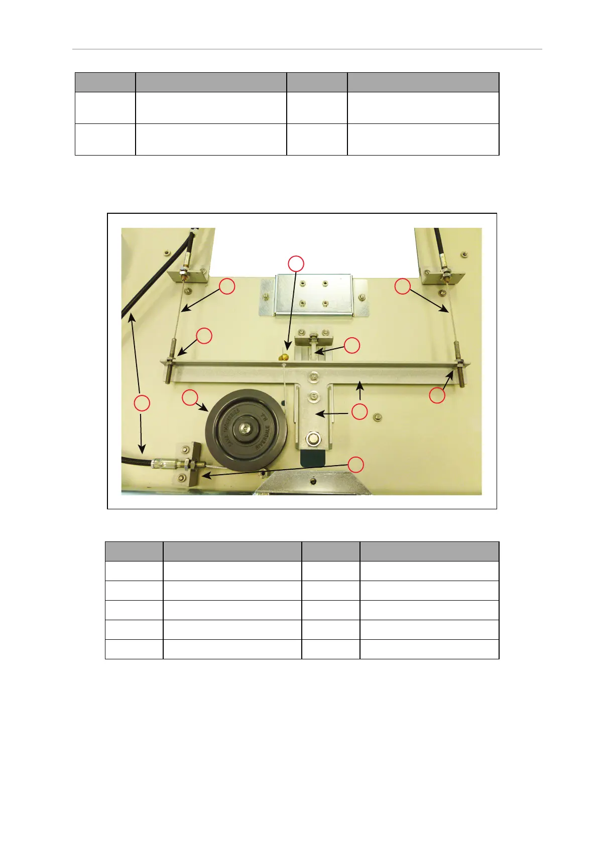
Figure 3-25. Internal Brake-Release Mechanism
Callout Description Callout Description
A Right Brake Cable F Actuator Bar
B Right Brake Adjust G Actuator Bar Hard Stop
C Lever Cable H Left Brake Cable
D Pulley I Left Brake Adjust
E Lever Cable Anchor K Lever Cable Clamp
2.
Route the cable to the lever cable anchor.
3.
Attach the actuator end of the cable to the lever cable anchor.