90 LD Cart Transporter User's Manual 14766-000 Rev H
6.3 Standard Platform Connections
Figure 6-5. Front Upper Core
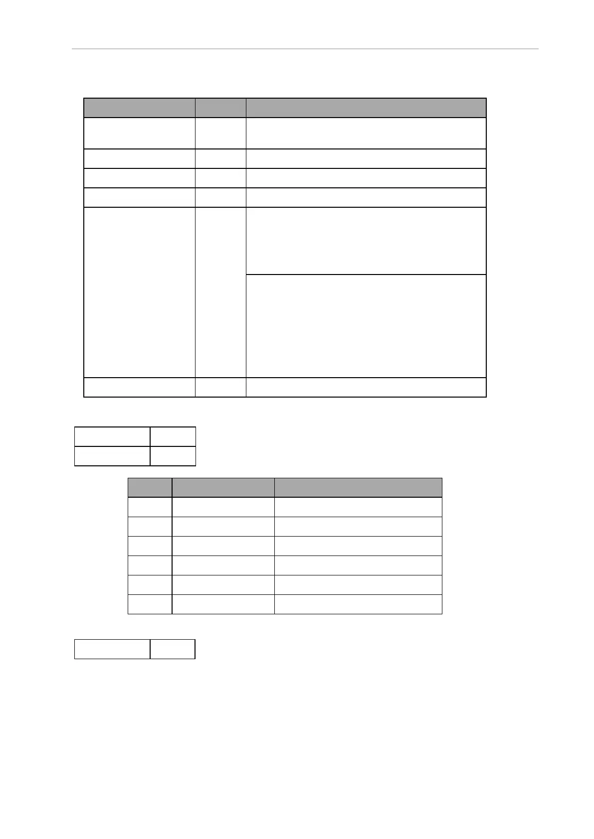
Connection Type Description
User LAN RJ45,
Shielded
General Ethernet, Auto-MDIX.
Aux Sensors HDB15M
Side lasers. The 13523-000L W cable is used to
split this port into three laser connectors.
RS-232 x 2 DB9M Port 1 and Port 2, general use
CAN Bus B DB9F Consult Support for use.
Digital I/O (HDB44F) HDB44F 16 digital inputs, in 4 banks of 4. Each bank can be
wired as active high or active low depending on the
connection of the BANK# terminal.
V
IN
range for each input is 0 to 30 V. The input is ON
when V
IN
> 4 V, OFF when V
IN
< 1.3 V.
16 digital outputs, protected low-side drivers. These
outputs should be wired to positive voltage through
the load. Output is open when OFF and grounded
when ON. Each open-drain output is capable of sink-
ing 500 mA. May be used with loads connected to
VBAT, AUX_20V, _12V, or _5V. You must stay
within the allowed current capacity of the VBAT or
AUX power supplies.
Analog I/O HDB15M General use
CAN Bus B
Connector type DB9F
Use CAN Bus
Pin No. Designation Notes
1, 4, 8 No Connection
2 CANL_B CAN Communication differential pair
3, 6 GND Direct GND
5 SHIELDGND Bead filter to GND
7 CANH_B CAN Communication differential pair
9 CANB_12V_OUT_SW 12 V @ 0.5 A Max (switched in SW)
Digital I/O
Connector type HDB44F