EasyManuals Logo

Omron NJ Series Startup Guide

Omron NJ Series
168 pages
To Next Page IconTo Next Page
To Previous Page IconTo Previous Page
Page #152 background imageLoading...
Page #152 background image
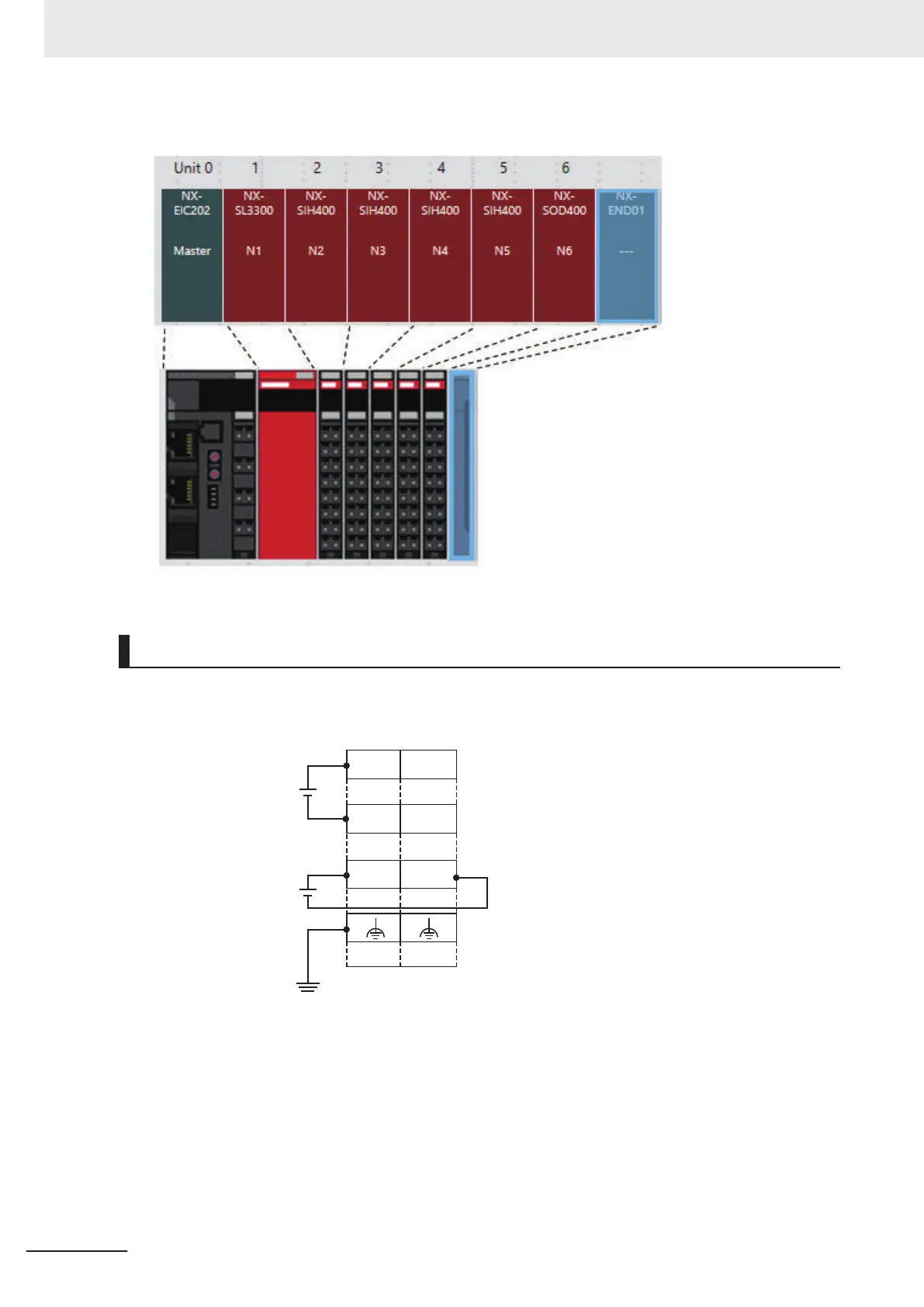
Wiring the Power Supplies
The power supply wirings and grounding for the EtherNet/IP Coupler Unit are shown in the figure be-
low.
IOV
UG
UV
IOG
UV
UG
A1
A8
B1
B8
Unit power supply
(20 VDC)
I/O power supply
(5 to 24 VDC)
Ground of 100 W or less
Connect the + terminal (24 VDC) of the Unit power supply to A1 or B1.
Connect the - terminal (0 VDC) of the Unit power supply to A3 or B3.
Connect the + terminal (5 to 24 VDC) of the I/O power supply to A5.
Connect the - terminal (0 VDC) of the I/O power supply to B5.
Connect the ground line to A7 or B7.
Appendices
A-8
NJ-series Robot Integrated System Startup Guide (O049)

Table of Contents

Other manuals for Omron NJ Series

Questions and Answers:

Question and Answer IconNeed help?

Do you have a question about the Omron NJ Series and is the answer not in the manual?

Omron NJ Series Specifications

General IconGeneral
Program CapacityUp to 128 MB
SD Card SlotYes
Power Supply Voltage24 VDC
Motion ControlYes
USB Ports1
Operating Temperature0°C to 55°C
Communication InterfacesEthernet/IP, EtherCAT, USB
Safety FunctionOptional
Storage Temperature-20°C to 75°C
Communication PortsUSB
DimensionsVaries by model
WeightVaries by model

Related product manuals