1-4
Hardware
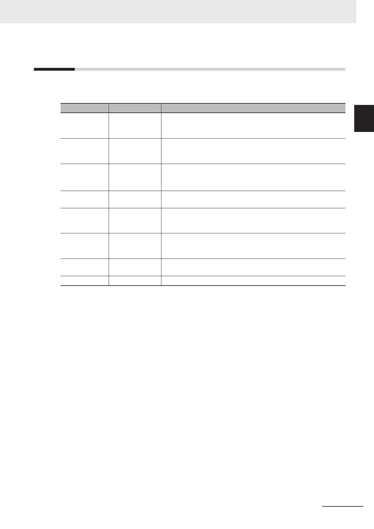
The following table shows an overview of each hardware in the system configuration.
Refer to the manual for the specific product for details.
Hardware Model Description
Robot Integrated
CPU Unit
NJ501-R£££
A CPU Unit that integrates the sequence control and robot control. To
use the robot control function, you must insert the included SD Memory
Card.
EtherCAT-com-
patible OMRON
robot
RL£-££££££
£
The OMRON robot that supports EtherCAT.
Computer --- A computer that the Sysmac Studio Automation Software to make the
settings for the robot integrated system and perform debugging is in-
stalled.
*1
Front Panel 90356-10358 A control panel for a robot. The panel has switches to change modes,
enable the high power
, and make a emergency stop.
T20 Pendant
10046-010 A teaching pendant for a robot. Use the pendant for teaching coordi-
nates. It has the built-in E-Stop button and built-in enable switch as
safety functions.
Safety circuits --- The safety circuits that consist of safety I/O devices, a Safety Control-
ler, etc. Refer to A-1 Designing Example of the Safety Functions for the
Pick-and-place Equipment on page A-2 for details.
Connected ex-
ternal devices
--- I/O devices connected to the digital I/O terminals of the robot.
EtherCA
T slaves --- EtherCAT slaves such as digital I/O, servos, and inverters.
*1. Refer to the Sysmac Studio Robot Integrated System Building Function with Robot Integrated CPU Unit
Operation Manual (Cat. No. W595) for information on the recommended operating environment for the com-
puter.
1 Overview
1-7
NJ-series Robot Integrated System Startup Guide (O049)
1-4 Hardware
1

 Loading...


