1-3 System Configuration
1-7
1-3 System Configuration
The following information describes the system configuration using NS-series PTs. Refer to
Appendix 8 Standard Models for details on available models.
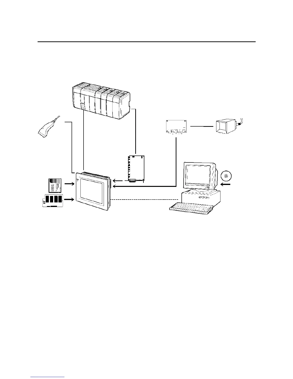
1-3-1 Supported Peripheral Devices
Note 1: Only the following models support Ethernet: NS12-TS01(B), NS10-TV01(B), and NS7-
SV01(B)
Note 2: Only the following models support the Controller Link Interface Unit and Video Input Unit:
NS12-TS0@, NS10-TV0@.
• PT (Refer to Appendix 8 Standard Models.)
• Recommended Bar Code Reader (Refer to page 3-12.)
OMRON V520-RH21-6
• Expansion Memory Board (Refer to page 3-15.)
OMRON NS-MF081 (8-MB flash memory)
OMRON NS-MF161 (16-MB flash memory)
• RS-232C/422A Converter
OMRON NS-AL002 (non-insulated) (Refer to page A-13.)
OMRON NT-AL001 (insulated)
Host
Bar Code Reader
Read bar codes
as text string data.
RS-232C cable
(15 m max.)
RS-422A cable
(500 m max.)
RS-232C/422A
Converter
Ethernet cable
(See note 1.)
Personal computer
Computer running Windows 95,
98, NT, Me, or 2000
NS-Designer
Memory Card
Save screen data or
the system program or
automatically read data
at startup.
Expansion Memory Board
Expand the area for screen
data.
RS-232C cable
Ethernet cable (See note 1.)
Twisted-pair cable
Video Input Unit
Video camera or
Vision Sensor
NTSC/PAL
cable
Controller Link
Interface Unit
enables Con-
troller Link com-
munications with
a host.
(See note 2.)

 Loading...


