2-2 Part Names and Functions
2-10
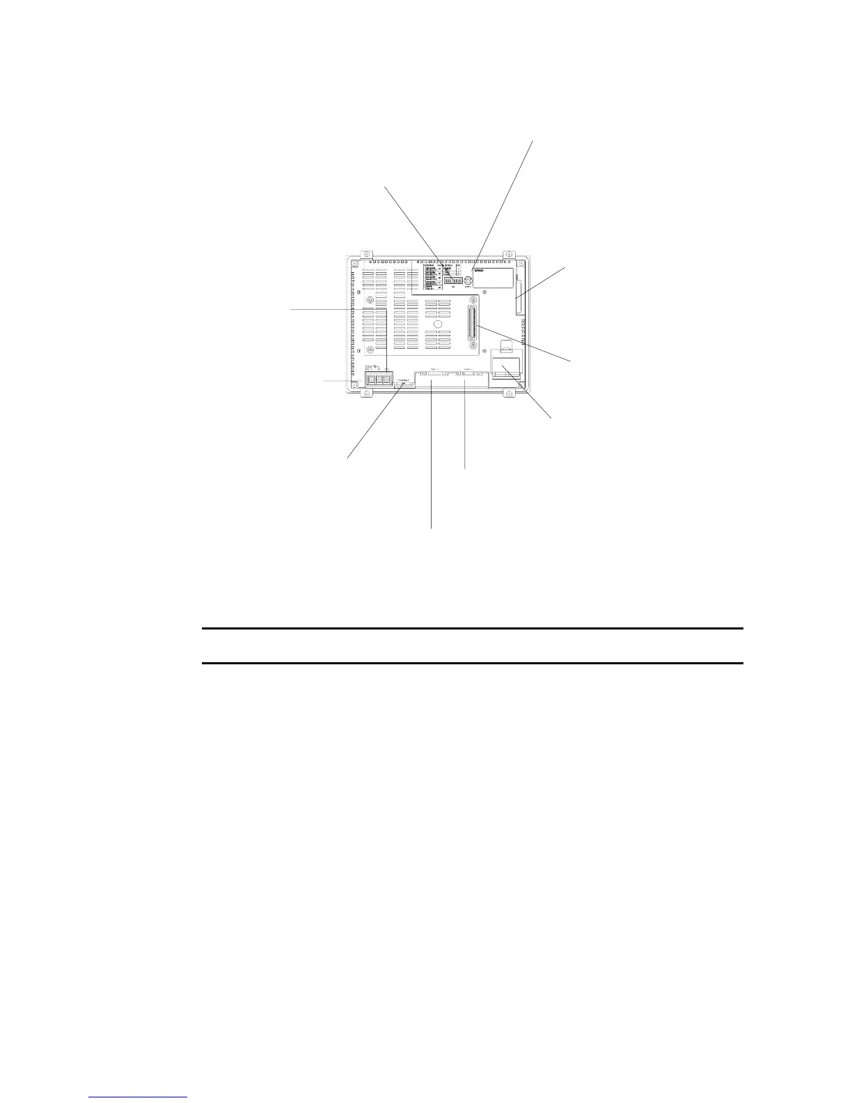
NS7 Rear Panel
Note: The 5-V output of serial ports A and B cannot be used at the same time.
Note Confirm system safety before turning the power ON/OFF or restarting. Otherwise the system
may operate unpredictably.
Reset Switch
Used to initialize the PT. The
statuses of screen data, other
registered data, and memory
switches will not change.
Serial Port A Connector (See note.)
Used to connect the host, NS-Designer, and
Bar Code Reader. Uses an RS-232C 9-pin
connector.
Serial Port B Connector (See note.)
Used to connect the host, NS-Designer, and Bar
Code Reader. Uses an RS-232C 9-pin connector.
Ethernet Connector
Used to connect the Ethernet cable.
Uses a 10Base-T 8-pin modular
plug.
Battery Cover
The battery is installed underneath
the cover.
Main Circuit DC Input
Terminal
Used to connect the
power supply.
FG Terminal
Used to prevent
malfunctions due to noise
interference.
DIP Switch
Used to set the settings for
transferring data using the memory
card.
Expansion Interface Connector
Used to mount the Expansion
Interface Unit.
Memory Card Connector
Used to connect the memory
card for storing and transfer-
ring screen data, log data,
and system programs.

 Loading...


