4-1 1:1 Host Connection
4-6
• Host Settings
The methods for setting each Unit are as follows:
Connecting C Series, C200HS, C200HX/HG/HE(-Z), CQM1, CPM2A, CPM2C, or
CQM1H PLCs
PLC Setup Area
Write the settings directly from the Programming Device (CX-Programmer, etc.) to the PLC
Setup Area (in DM Area) according to the host type and port used.
Using RS-232C
Host type Address Write value Settings
Built-in RS-232C port of C200HS, C200HX/HG/HE(-Z),
CPM1A, CPM2A, CPM2C, CQM1, or CQM1H
DM 6645
Port A of C200HX/HG/HE(-Z) (See note 1.)
Port 1 of CQM1H (See note 2.)
DM 6555
Port B of C200HX/HG/HE(-Z) (See note 1.) DM 6550
4000 Uses 1:1 NT
Link
Note 1. RS-232C port of Communications Board.
2. RS-232C port of Serial Communications Board.
Using RS-422A
Host type Address Write value Settings
Port A of C200HX/HG/HE(-Z)
(See note 1.)
DM 6555 4000
Port 2 of CQM1H (See note 2.) DM 6550 4000
Uses 1:1 NT
Link
Note 1. RS-422A port of Communications Board.
2. RS-422A port of Serial Communications Board.
Refer to the manuals of the PLC being used for details on using the PLC Setup Area.
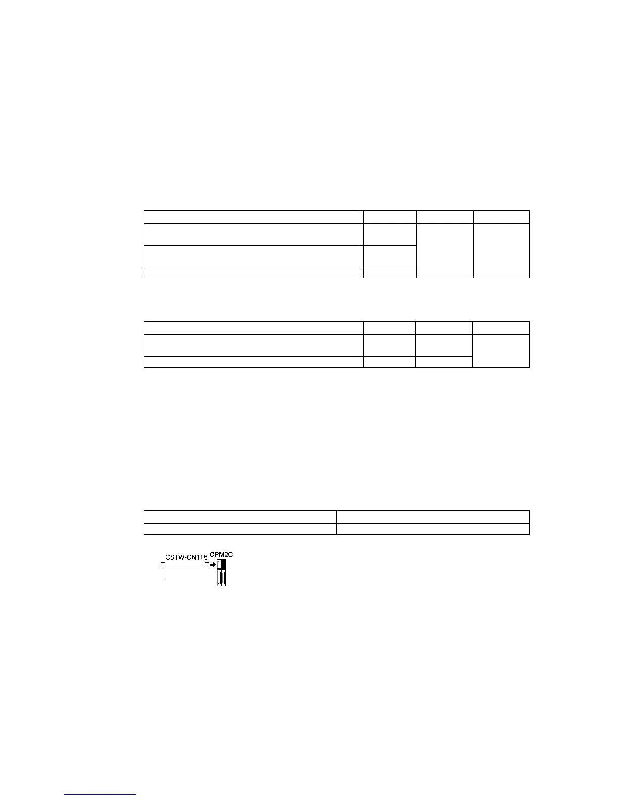
Connecting to CPM2C PLCs
The CPM2C has a single connector that is the same shape as a CS-series peripheral port.
Internally, the connector has signal lines that are for use with the CPU’s built-in RS-232C port
and the peripheral port. Therefore, when using the CPM2C, use the settings for the CPU’s
built-in RS-232C port or for the peripheral port according to the converter cable and port
used, as follows: Refer to the CPM2C Operation Manual (W356) for details.
Port for connecting PT PLC Setup
CS1W-CN118 port (D-Sub 9-pin) Set for built-in RS-232C.
Setting the Front Panel DIP Switch
Using RS-232C
When using C200HX/HG/HE(-Z), CQM1, or CQM1H PLCs, set the DIP switch on the front
panel to enable the PLC Setup Area (Data Memory) settings, as follows:
RS-232C port
(D-Sub 9-pin female)

 Loading...


