4-2 1:N Host Connection
4-14
Setting the Communications Board Switches
• Using RS-422A
Set the switches of the C200HX/HG/HE(-Z) Communications Board, as follows:
Switch 1: 4
(Four-wire method = RS-422A)
Switch 2: ON (terminator ON = terminating resistance used)
Set the switches of the CQM1H Serial Communications Board as follows:
Two-wire/four-wire switch (WIRE): 4 (Four-wire method = RS-422A)
Terminating resistance switch (TERM): ON (terminator ON = terminating resistance used)
Connecting to CS-series CPU Units
CS-series CPU Units:
CS1G/H-CPU@@-E(V1) and CS1G/H-CPU@@H
PLC Setup Area
• Using RS-232C
When connecting the PT to a CS-series CPU Unit, set the communications conditions in the
PLC Setup according to the communications port used, as follows:
Using Built-in RS-232C Port of CS1G/H or CS1G/H-H
Address Write value Settings
160 8200 1:N NT Link Mode
161 0000 to 0009 (See note 1.) Baud rate (normal)
166
000@@: Largest unit number (1 to 7) of the connected
PTs. (See note 2.)
Note 1. Set the baud rate to a numeric value between 0000 to 0009 Hex. (The setting is the same for
any value between 0000 and 0009 Hex.)
2. When using a 1:N connection, set the value for @ to 1 or higher.
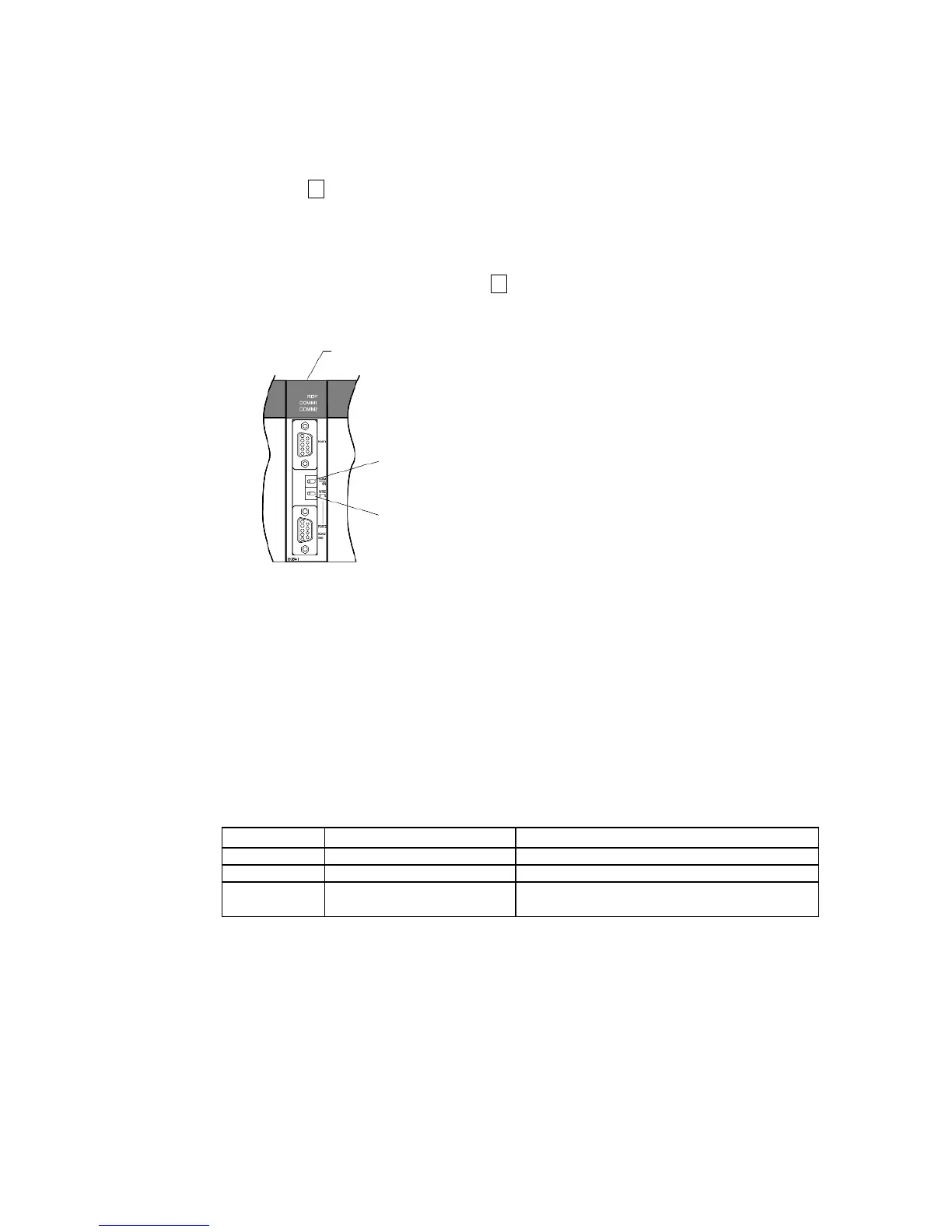
Serial Communications Board (Inner Board slot 1)
Terminating resistance switch
Set to ON (right position).
Two-wire/four-wire switch
For RS-422A: Set to 4 to use four-wire (right position).
 Loading...


