5-1 Connecting to Host Via Ethernet
5-10
Reference
· When using automatic generation (default method) for converting addresses, set the
same value for the node number as that set for SW7 and SW8, and set the other host
ID fields to 0. The ERC indicator will flash if the value of the IP address host ID does
not correspond to the node number value.
· Set the subnet mask in the CPU Bus Unit Setup Area using the CX-Programmer.
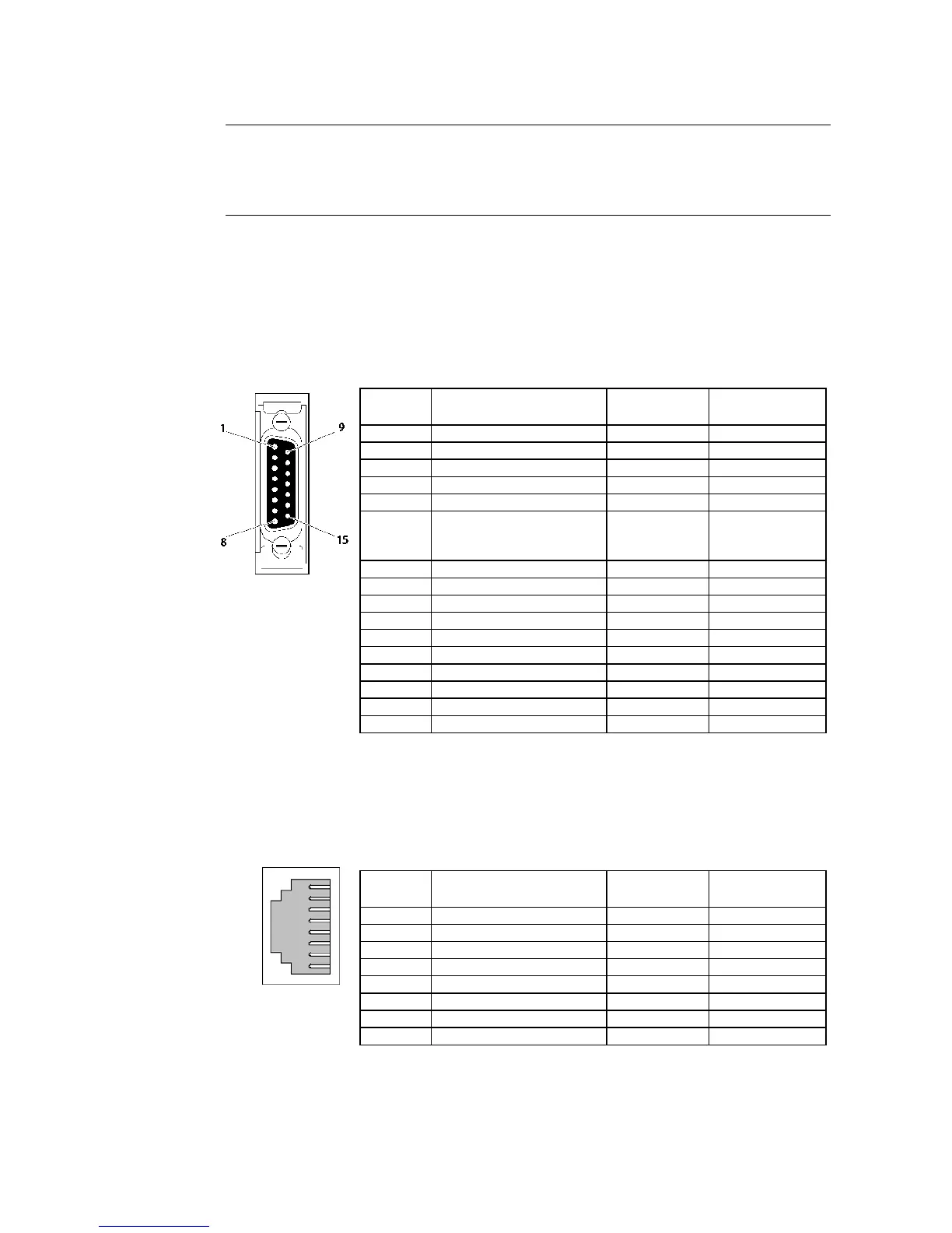
Ethernet Connectors:
CS1W-ETN01
This is the connector used to connect the transceiver cable to the Ethernet.
· Electrical characteristics: Conforms to IEEE802.3 standards.
· Lock structure: Conforms to IEEE802.3 standards for Slide latches.
Connec-
tor Pin
Signal name Abbreviation Signal direction
1 Signal ground GND
-
2 Collision detection signal + COL+ Input
3 Send data + TX+ Output
4 Signal ground GND -
5 Receive data + RX+ Input
6 Voltage common
Power ground (common
with signal ground)
VC -
7 Not used. -
8 Signal ground GND -
9 Collision detection signal - COL- Input
10 Send data - TX- Output
11 Signal ground GND -
12 Receive data - RX- Input
13 Transceiver power VP -
14 Signal ground GND -
15 Not used. --
Hood Frame ground FG -
CS1W-ETN11
This is the connector used to connect the twisted-pair cable to the Ethernet.
· Electrical characteristics: Conforms to IEEE802.3 standards.
· Connector structure: RJ45 8-pin modular connector (conforms to ISO8877).
Connec-
tor Pin
Signal name Abbreviation Signal direction
1 Send data + TD+ Output
2 Send data - TD- Output
3 Receive data + RD+ Input
4 Not used. --
5 Not used. --
6 Receive data - RD- Input
7 Not used. --
8 Not used. --
1
8
 Loading...


