91
Connecting to the Host’s RS-232C Port Section 5-1
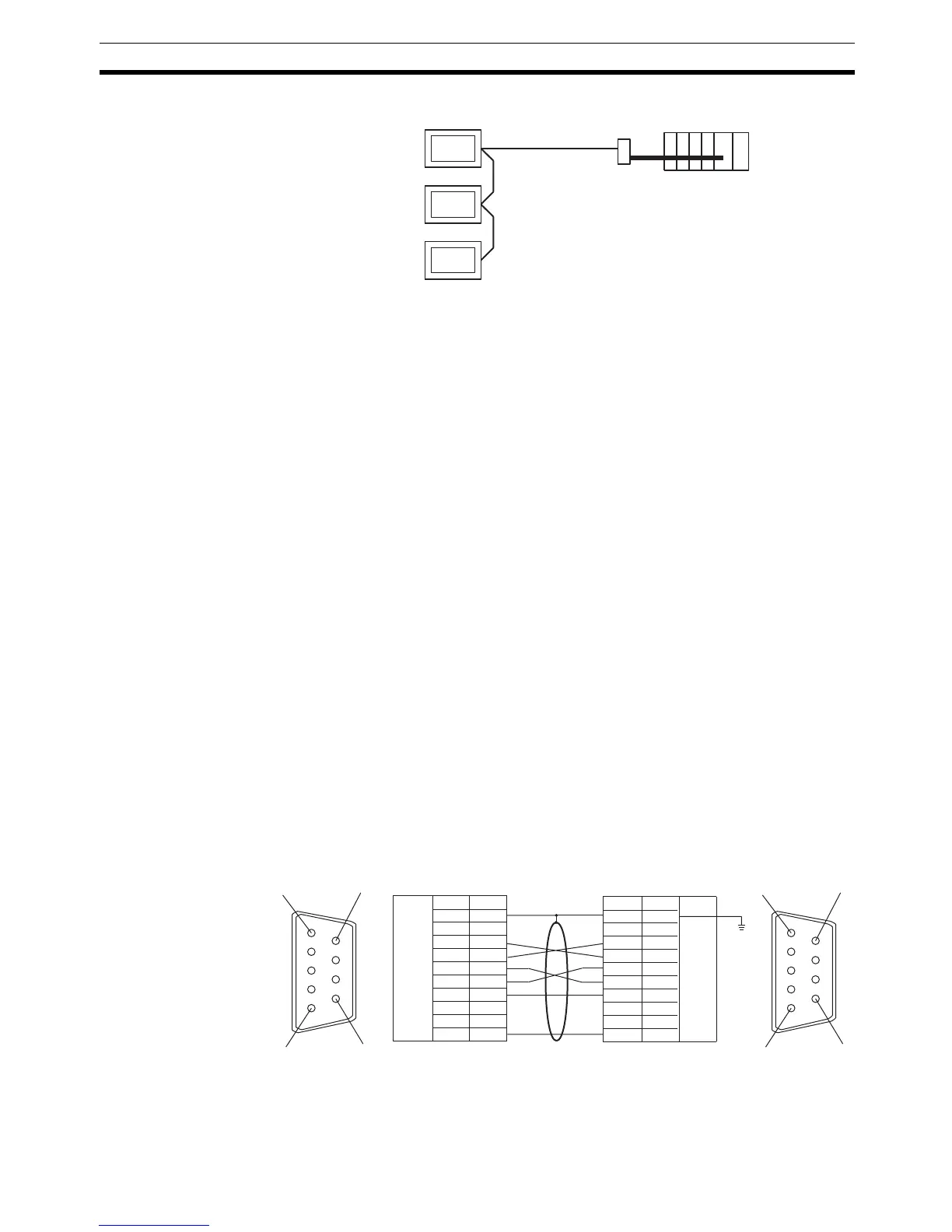
Connecting an NT-AL001 and Host
Wiring when connecting a CS-series Serial Communications Board, CS/CS-
series Serial Communications Unit, CQM1H Serial Communications Board, or
C-series C200HX/HG/HE(-Z)E Communications Board.
Applicable PLCs:
Note A Serial Communications Board cannot be used.
Usable Cables with Attached Connectors:
• For host link, 1:1 NT Link, or 1:N NT Link (+5 V power supplied from PLC)
XW2Z-070T-1(9-pin to 9-pin, 0.7 m)
XW2Z-200T-1(9-pin to 9-pin, 2 m)
SJ46006-102(9-pin to 9-pin, 1 m)
SSJ46006-202(9-pin to 9-pin, 2 m)
Since the CS1G/H, CQM1H, and C200HX/HG/HE(-Z)E have a +5 V out-
put, no external power supply is required for the NT-AL001.
CS1W-SCU21(-V1)
CJ1W-SCU21(-V1)/CJ1W-SCU41(-V1)
CS1G-CPU42/43/44/45-E(V1)
CS1H-CPU63/64/65/66/67-E(V1)
CS1G-CPU42H/43H/44H/45H
CS1H-CPU63H/64H/65H/66H/67H
CS1D-CPU65H/67H
CJ1G-CPU44/45
CJ1G-CPU42H/43H/44H/45H
CJ1H-CPU65H/66H/67H
CJ1M-CPU11/12/13/21/22/23
CQM1H-CPU51/61
C200HE-CPU32/42-(Z)E
C200HG-CPU33/43/53/63-(Z)E
C200HX-CPU34/44/54/64-(Z)E
C200HX-CPU65-ZE/85-ZE
RS-232C
NT31/NT31C
Host
NT-AL001
6
5
9
1
6
5
9
1
Shielding wire
(9-pin type)
NT-AL001 side
FG
−
SD
RD
RS
CS
+5V
−
−
SG
1
2
3
4
5
6
7
8
9
Abbreviation
Pin number
Connector
hood
RS-232C
connector
(9-pin type)
FG
−
SD
RD
RS
CS
+5V
−
−
SG
1
2
3
4
5
6
7
8
9
Abbreviation
Pin number
Connector
hood
RS-232C
connector
PLC side

 Loading...


