7
Functions of the NT31/NT31C Section 1-2
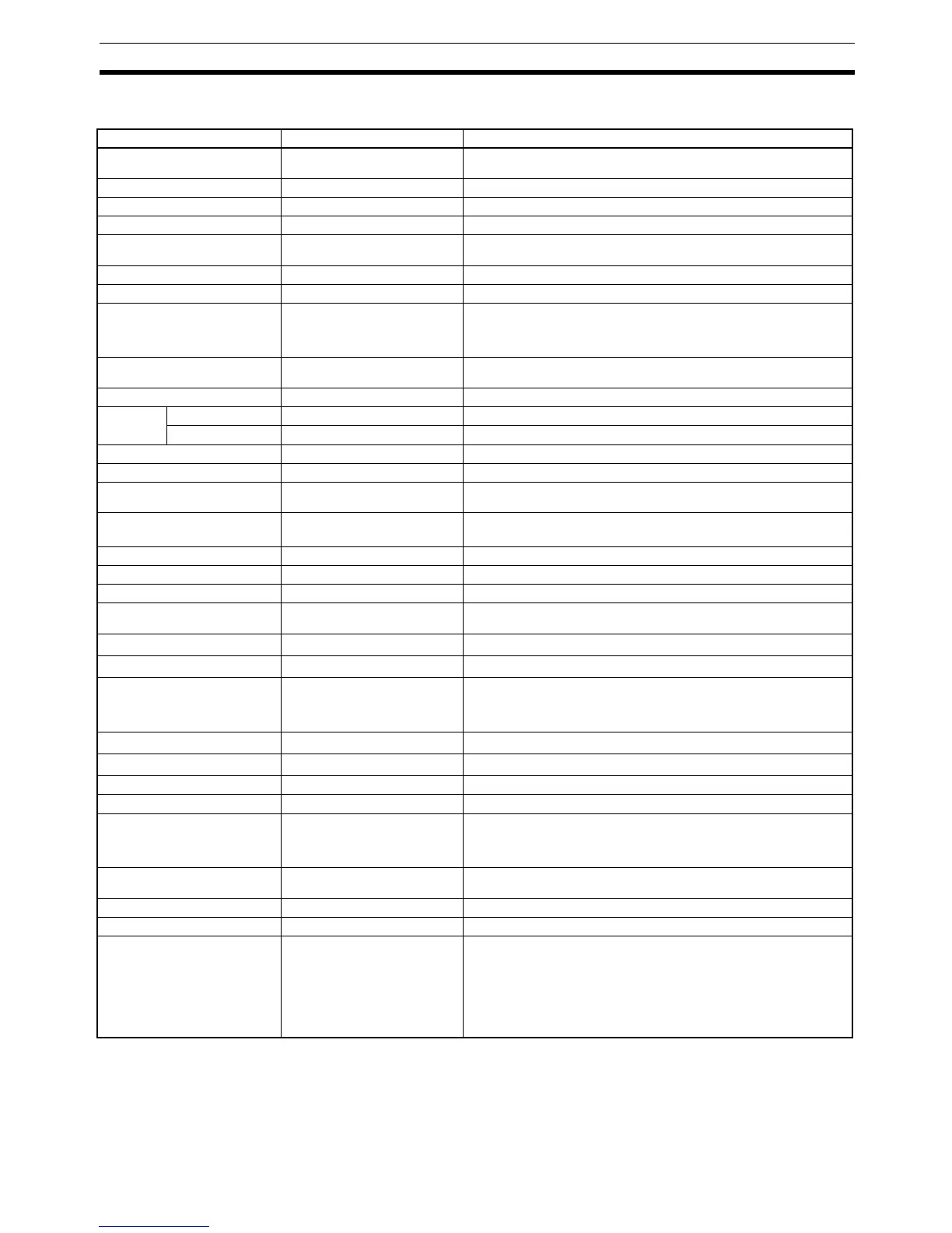
1-2-3 Comparison between NT30/NT30C and NT31/NT31C
*1
This is the capacity of the flash memory that stores screen data.
*2
The values are the same as the NT30/NT30C when the PT is in NT30/620 compatible mode.
For differences in programming, refer to Appendix B in the NT31/NT31C/NT631/NT631C Programmable Termi-
nal Reference Manual.
Item NT30/NT30C NT31/NT31C
Support Tool used NT-ZJCAT1-EV4 or NT-ZA3AT-
EV2
NT-ZJCAT1-EV4
DIP switches On rear of PT None (software settings)
Use of B7A Unit Possible Not possible
Use of Memory Unit Not possible Possible
RS-232C interface Connector (9-pin) also used as
port for screen data transfer.
• Serial port A connector (also used for screen data transfer, 9-pin)
• Serial port B connector (for host communications only, 25-pin)
RS-422A/485 interface Terminal block Serial port B (25-pin D-SUB connector)
Backlight color White/red (selectable) White only
Replacement backlight NT30-CFL01/NT30C-CFL01 NT31C-CFL01 (Same for both the NT31-ST121@-EV2 and NT31C-
ST141@-EV2).
The backlight cannot be replaced by the user for the NT31-ST122@-EV2,
NT31C-ST142@-EV2, NT31-ST123@-EV3, and NT31C-ST143@-EV3.)
NT31/NT31C system program
data
NT-ZS3AT-EV1
(including system installer)
The system installer and system program data are supplied with the Sup-
port Tool.
High-speed 1:N NT Link Not possible Possible
Memory
Link
System program Exclusive use by Memory Link Same as OMRON connection
Screen data Shared with OMRON connection Exclusive use by Memory Link
LCD contrast adjustment By a control on the rear of the PT By touch panel operation
Backlight brightness adjustment Not possible By touch panel operation
Number of user-registered
screens
Maximum of 2000 Maximum of 3999
Screen data capacity
*1
(User program memory)
512 KB 1 MB
Numeral string data Maximum of 1000 Maximum of 2000
Character string data Maximum of 1000 Maximum of 2000
Bit data 256 Maximum of 1000
Mathematical tables None 256 max.
Calculations can be executed automatically in the PT.
Image data Maximum of 224
Maximum of 4095
*2
Library data Maximum of 896
Maximum of 12288
*2
Method for storing numeric val-
ues
(numeral memory data and PT
status control area)
Fixed as BCD (binary coded dec-
imal)
Selectable from BCD (binary coded decimal) or binary
PT status control area size 4 words
5 words (partial change of contents)*
2
PT status notify area size 3 words
2 words (partial change of contents)*
2
Window control area size None 9 CH
Registering continuous screen Possible Not possible (Use a screen switchover as a substitute.)
Lamp/Touch switch labels Fixed display (1 line only) • Multiple lines can be displayed
• ON/OFF switching is possible
• Numeral display is possible
• Character string display is possible
Interlock function None Operations can be disabled from the PLC by allocating interlock bits to
the corresponding touch switch, numeral input, or character string input.
Device monitor function Not possible Possible
Recipe function None Possible
Accessible CS/CJ-series PLC
data areas
--- The data areas listed below can be accessed in addition to the data
areas accessible with the NT30/NT30C.
• EM banks (EM_0 to EM_C)
• Timer completion flags (TU)
• Counter completion flags (CU)
• Work areas (WR)
•Task flags (TK)
• HR area

 Loading...


