38
Using a Memory Unit Section 3-5
3-5-2 Method of Use
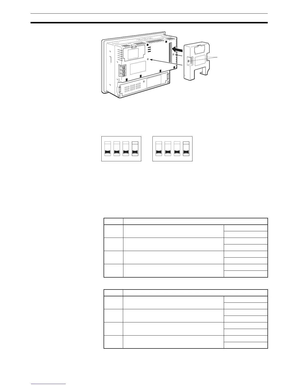
As shown in the figure below, a Memory Unit has two sets of four DIP
switches, and the operation is determined by the DIP switches that are set at
startup.
Note 1. Always confirm that the power to the NT31/NT31C is off before setting the
DIP switches.
2. Do not touch the PCB (printed circuit board) directly with bare hands.
DIP Switch Functions The functions of the DIP switches on the Memory Unit are indicated in the
table below.
•SW1
•SW2
Mounting screws
4321
OFF
SW1 SW2
OFF
4321
Factory setting is turned all to off.
Switch Function
SW1-1 Automatic transmission (writing from the Memory
Unit to the PT)
OFF: Not executed
ON: Executed
SW1-2 Automatic transmission (writing from the PT to the
Memory Unit)
OFF: Not executed
ON: Executed
SW1-3 Manual transmission (Direction of transmission
and bank used selected at the PT touch panel)
OFF: Not executed
ON: Executed
SW1-4 Data type to transfer OFF: Screen data
ON: System program
Switch Function
SW2-1 Disable/enable writing to PT OFF: Disable
ON: Enable
SW2-2 Disable/enable writing to the Memory Unit OFF: Disable
ON: Enable
SW2-3 Area (bank) selection of automatic transmission. * OFF: Bank 0
ON: Bank 1
SW2-4 System/Screen simultaneous transmission OFF: Disable
ON: Enable

 Loading...


