32
Installation Section 3-1
Tighten the screws on the terminal block to a torque of 0.8 N⋅m.
Recommended Terminals
Note Conformance to Shipbuilding Standard
• Use gaskets or other materials to completely shield all openings and
other gaps in the control panel.
• Use copper tape or other electrically conductive tape to shield gaps
between the cutout and the PT before securing the PT in place.
• To suppress noise terminal voltage, perform installation under the follow-
ing conditions. It is recommended to use the following product for the DC
power supply.
Recommended Power Supply model: S82K-03024
Manufacturer: OMRON
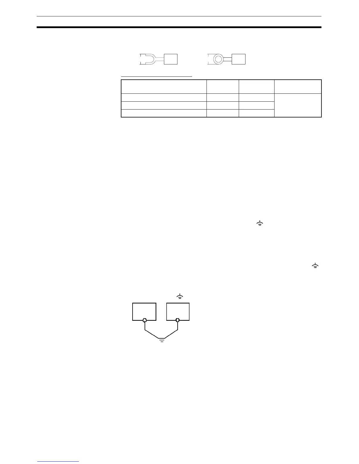
3-1-4 Grounding
The NT31/NT31C has a functional ground terminal ( ).
Carry out wiring under the following conditions.
1,2,3... 1. In cases where there is a potential difference between the grounds of the
NT31/NT31C and the host, ground as shown in the following figure. If there
is some distance between the NT31/NT31C and host and grounding at a
single point is difficult, do not connect the functional ground terminal ( )
of the NT31/NT31C.
2. If the NT31/NT31C is installed in the same panel as equipment that gen-
erates noise, such as a motor or inverter, do not ground the functional
ground terminal ( ) of the NT31/NT31C.
Note Carry out grounding correctly in order to prevent operating errors due to
noise.
Maker Type
(fork type)
Type
(round type)
Applicable Wire
(stranded wire)
Japan Solderless Terminal MFG 2-YS3A 2-3.5
2.0 to 2.63 mm
2
Fuji Terminal 2-YAS3.5 V2-S3.5
Nichifu Terminal 2Y-3.5 2-3.5
Fork type Round type
7 mm max. 7 mm max.
Host
NT31/
NT31C
Grounding at
a single point

 Loading...


