100
Connecting to the Host’s RS-422A/485 Port Section 5-2
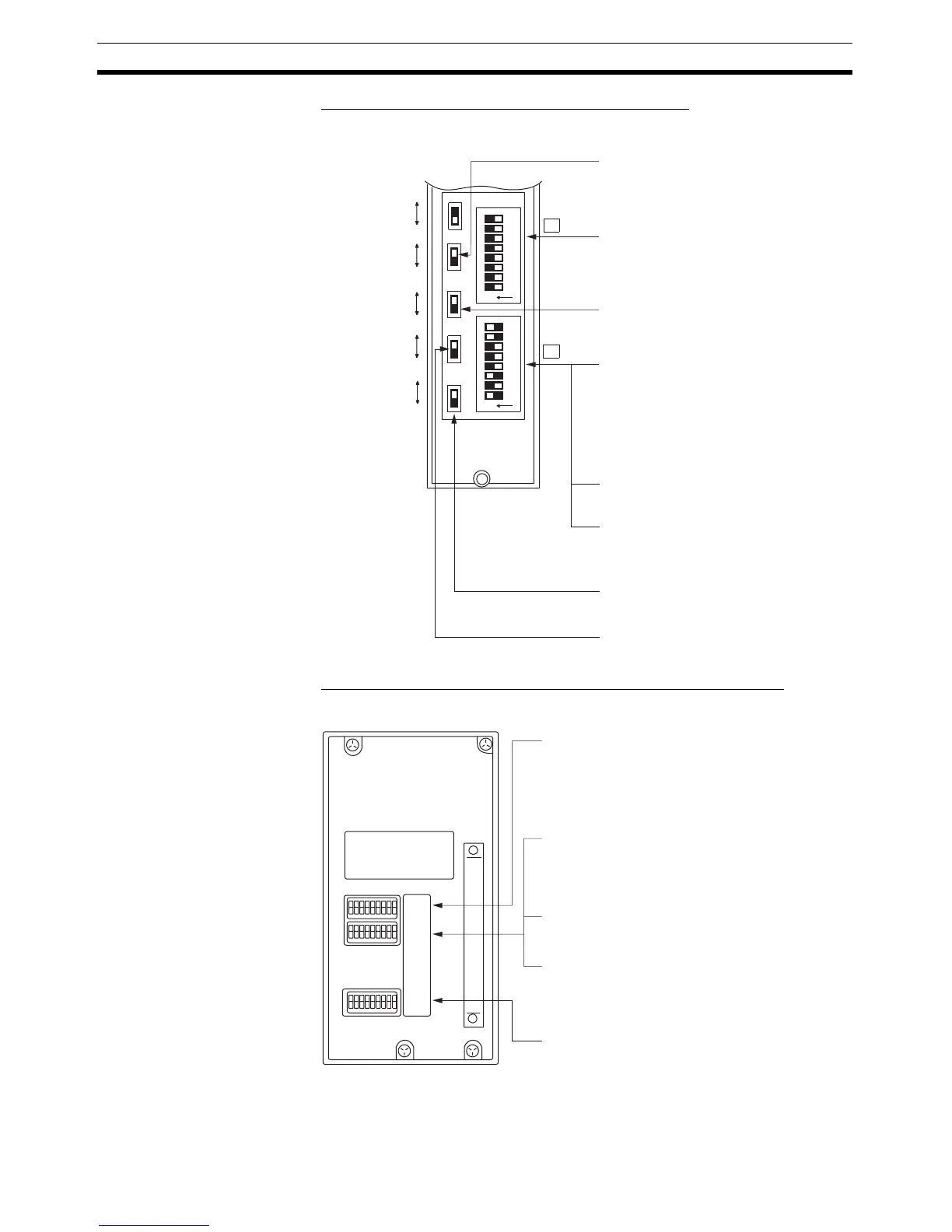
C1000H/C2000H Rack-mounting Unit: C500-LK203
Setting the Rear Switches
C200H/C1000H/C2000H CPU-mounting Unit: 3G2A6-LK202-EV1
Setting the Rear Switches
I/O port
RS-422A
RS-232C
Synchronization
Internal
External
Terminator
OFF
ON
CTS
0 V
External
• I/O port selection (selector switch)
Set this to RS-422A.
• Synchronization (selector switch)
Set this to Internal.
• Communications speed
(DIP SW2-1 to SW2-4)
• 1-to-1/1-to-N selection (DIP SW2-6)
Set SW2-6 to OFF (0) (1-to-N).
• Instruction level (DIP SW2-7, SW2-8)
Set these switches to ON (1).
(Levels 1, 2, and 3 are enabled.)
5 V supply
ON
OFF
• Unit #, parity, and transfer code
(DIP SW1-1 to SW1-7)
Set SW1-1 to SW1-7 to OFF (0).
• CTS selection (selector switch)
Set this always to 0 V (ON).
• Terminator setting (selector switch)
Set this switch to ON.
SW1
SW2
1
2
3
4
5
6
7
8
1
2
3
4
5
6
7
8
ON
ON
Set these switches to 0010 to select
19,200 bps.
Set these switches to 1010 to select
9,600 bps.
(0: OFF 1: ON)
SW1
SW2
SW3
• Unit #, parity, and transfer code
(DIP SW1-1 to SW1-5)
Set SW1-1 to SW1-5 to OFF (0).
• Communications speed (DIP SW2-1 to SW2-4)
Set these switches to 0010 to select 19,200 bps.
Set these switches to 1010 to select 9,600 bps.
(0: OFF 1: ON)
• 1-to-1/1-to-N selection (DIP SW2-6)
Set SW2-6 to OFF (0) (1-to-N).
• Instruction level (DIP SW2-7, SW2-8)
Set these switches to ON (1).
(Levels 1, 2, and 3 are enabled.)
• Terminator setting (DIP SW3-1 to SW3-6)
Set SW3-1, SW3-3, and SW3-5 to ON (1).
Set SW3-2, SW3-4, and SW3-6 to OFF (0).
(Set terminator ON.)
* Parity is fixed at Even Parity. Transfer code is
fixed at ASCII 7 data bits and 2 stop bits.

 Loading...


