114
Connecting to the Host’s RS-422A/485 Port Section 5-2
*2
This CPU Unit is for a Duplex-CPU Unit System. The CS1W-SCB41(-V1)
Serial Communications Board cannot be used. Use the CS1W-SCU31-V1
Serial Communications Unit.
*3
A CS1W-SCU31-V1 or CS1W-SCU41(-V1) Serial Communications Unit is
required.
Settings at the Host
Connecting to a CS-series Serial Communications Board
Serial Communications Board equipped with an RS-422A/485 port for CS-
series CPU Units:
CS1W-SCB41(-V1) (Port 2 is an RS-422A/485 port.)
Reference: CS-series Serial Communications Boards and Units with lot number 991220
(December 20, 1999) or later support the high-speed 1:N NT Link method.
Boards and Units with earlier lot numbers cannot be used.
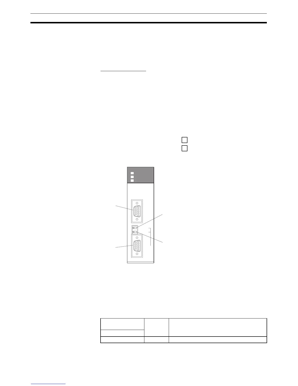
Setting the Front Switches
Set the switches on the Serial Communications Board as shown below.
2-wire or 4-wire selector (WIRE): (4-wire = RS-422A), or
(2-wire = RS-485)
Terminating resistance switch (TERM): ON (terminator ON = terminating
resistance enabled)
CPU Unit Allocation DM Area Settings
Setting is written from the Programming Device (a Programming Console or
CX-Programmer) directly into the allocation DM area (system setting area) of
the CPU Unit. After the setting is written, it becomes effective by turning the
power ON, restarting the Unit, restarting the communications port, or execu-
tion of the STUP command.
In the following table, the relevant word addresses in the allocation DM area
and settings are shown.
Allocated DM Area
words
Setting Setting Contents
Port 2
DM32010 8200 N1:N NT Link Mode
4
2
Port 1
RS-232C
Port 2
RS-422A/485
PORT1
ON TERM
4 WIRE
OFF
2
PORT2
(RS422/
RS485)
RDY
COMM1
COMM2
SCB41
Terminator Switch (TERM)
Set to ON (right side).
Wire Selection Switch (WIRE)
RS-422A: Set to 4 (right side) for 4-wire type.
RS-485: Set to 2 (left side) for 2-wire type.

 Loading...


