52
Connecting to the RS-232C Port at the Host Section 4-1
C200H/C1000H/C2000H CPU-mounting Unit: 3G2A6-LK201-EV1
Setting the Rear Switches
Connecting to a CVM1/CV
Series Host Link Unit
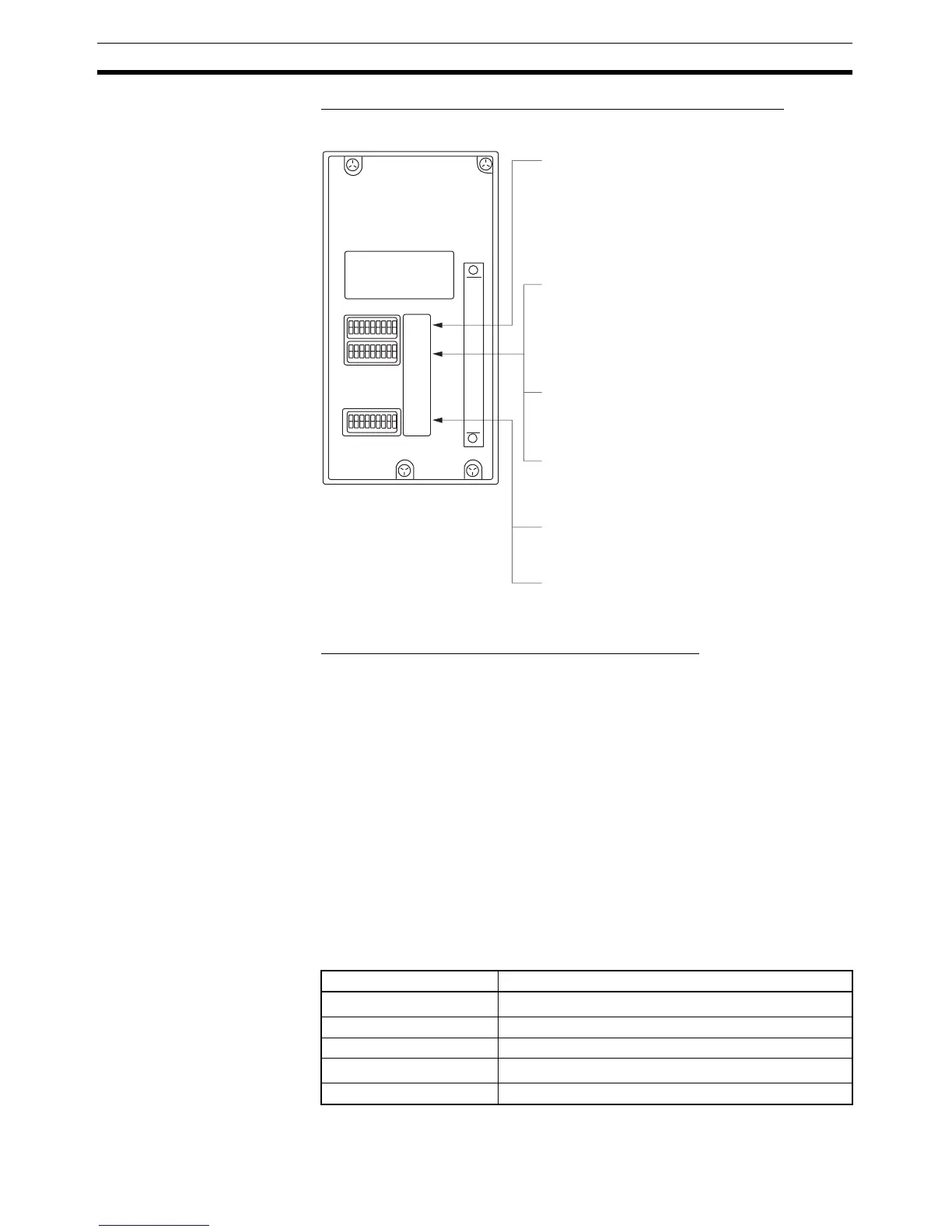
CVM1/CV-series Rack-mounting Unit: CV500-LK201
A CVM1/CV series Host Link Unit (CV500-LK201) has two connectors (com-
munications ports 1 and 2). Either of these ports can be used for connection
to an NT31/NT31C by the RS-232C method. However, since the connectors
at these ports are of different types, a cable that matches the connector must
be prepared.
• Communications port 1
Communications port 1 is a 25-pin connector for RS-232C use only.
• Communications port 2
Communications port 2 is a 9-pin connector which allows selection of the
RS-232C or RS-422A method. When this port is used with the RS-232C
method, the I/O port selector switch on the front of the Unit must be set to
RS-232C (the upper position).
CPU Bus Unit Settings
When connecting to a CVM1/CV-series Host Link Unit, set the following com-
munications conditions for the CPU Bus Unit settings.
SW1
SW2
SW3
• Unit #, parity, and transfer code
(DIP SW1-1 to SW1-5)
Set SW1-1 to SW1-5 to OFF (0).
• Communications speed (DIP SW2-1 to SW2-4)
Set these switches to 0010 to select 19,200 bps.
Set these switches to 1010 to select 9,600 bps.
(0: OFF 1: ON)
• 1-to-1/1-to-N selection (DIP SW2-6)
Set SW2-6 to OFF (0) (1-to-N).
• Instruction level (DIP SW2-7, SW2-8)
Set these switches to ON (1).
(Levels 1, 2, and 3 are enabled.)
• CTS selection (DIP SW3-1 and SW3-2)
Set SW3-1 to ON (1), and SW3-2 to OFF (0).
(Set this always to 0 V.)
• Synchronization (DIP SW3-3 to SW3-6)
* Parity is fixed at Even Parity. Transfer code is
fixed at ASCII 7 data bits and 2 stop bits.
Set SW3-3, and SW3-5 to ON (1), and SW3-4,
and SW3-6 to OFF (0). (Set these to Internal.)
Item Setting at Host
Communications speed
Set the same speed as set at the NT31/NT31C
(*1)
Transfer code ASCII, 7 data bits, 2 stop bits
Parity Even
1-to-1, 1-to-N
1-to-N
(*2)
Instruction level Level 1, 2, 3
 Loading...


