58
Connecting to the RS-232C Port at the Host Section 4-1
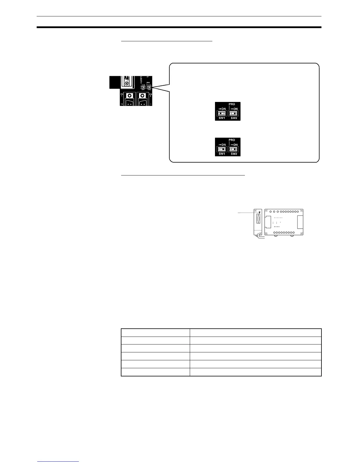
Setting the Switches of a CPM2C
When using a CPM2C, the switches on the front panel must be set as shown
below in order to make the PLC Setup settings effective.
Setting the Switches on an RS-232C Adapter
When using a CPM1-CIF01 RS-232C Adapter, set the mode switch as shown
in the following diagram.
CS/CJ-series CPU Unit: CS1G/H-CPU@@-E(V1), CS1G/H/D-CPU@@H-E,
CJ1G/M-CPU@@, CJ1G/H-CPU@@H
Connect to the built-in RS-232C port of the CPU Unit, or the RS-232C port of
the Communications Board. Note that the connection to a peripheral port
must be made via an RS-232C Adapter (CS1W-CN118) specially designed
for connecting to a peripheral port.
PLC Setup
When connecting to a CS/CJ-series CPU Unit, set the following communica-
tions conditions for the PLC Setup area. Since the settings shown below are
the PLC default settings for the CPU Unit, no change to the PLC Setup is nec-
essary as long as the communications speed is maintained at 9600 bps.
*1
Set the host link communications speed at 9600 bps or 19200 bps with the
memory switch at the NT31/NT31C. For details, refer to 6-7-2 Setting the
Host Link Method (page 161). When the communications speed is set to
19200 bps, the PLC Setup of the CPU Unit need to be changed.
• Connecting PT to peripheral port
• Connecting PT to built-in RS-232C port
SW1: OFF
SW2: ON
• Connecting PT to built-in RS-232C port
(A Programming Console is connected to the peripheral port.)
SW1: OFF
SW2: OFF
(A device that requires non-standard communications
settings is connected to the peripheral port.)
The settings for SW1 and SW2 depend upon the usage of the
peripheral port and RS-232C port.
Item Setting at Host
Communications speed Set the same speed as set at the NT31/NT31C(*1)
Stop bits 2 stop bits
Parity Even
Data length ASCII 7 bits
Unit No. for the host link 00
CPM1
Set the mode setting switch to HOST (upper position).
CPM1-
CIF01

 Loading...


