4 Safety Function Blocks
4 - 6
NX-series Safety Control Unit Instructions Reference Manual (Z931)
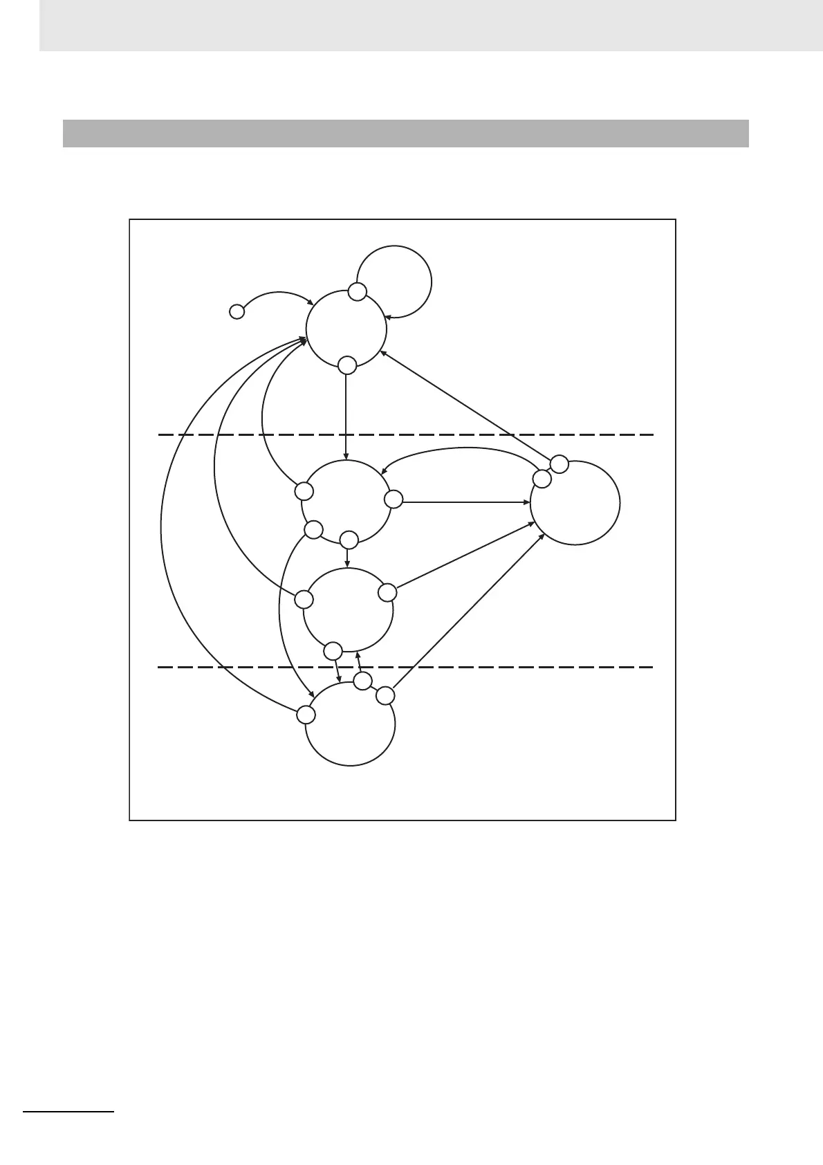
The following type of transition diagram shows changes in the state of the safety FB. This section
describes how to interpret state transition diagrams.
• The above diagram outlines the state transitions that apply to all safety FBs. Transitions that have
specific meanings for some FBs are not given here. They are described individually for the applicable
FBs.
• This diagram is separated into three parts.
In the top part, the FB is not operating and is in the safe state (i.e., safety outputs are FALSE).
In the middle part, the FB is operating and is in the safe state (i.e., safety outputs are FALSE).
In the bottom part, the FB is operating normally (i.e., safety outputs are TRUE).
• The dotted line at the top of the state transition diagram indicates transitions from not active to active.
The dotted line at the bottom of the diagram indicates transitions from the safe state to the normal
state of the FB.
• The priority of parallel transitions are shown with numbers. The highest priority is 0.
• The circles that indicate the states give the status name and the hexadecimal value of DiagCode.
• OR, AND, and XOR are used as logical operators and NOT is used as the logical negator to indicate
status.
Safety FB Common State Transition Diagram
NOT Activate
START
NOT Activate
ActivateNOT Activate
Idle
0000
0
0
0
1
NOT Activate
NOT Activate
1
1
2
3
1
On all errorsOn all errors
On all errors
0
2
1
2
0
Ready =FALSE
Ready =TRUE
ALL states
Error
2#11xx_xxxx_
xxxx_xxxx
R_TRIG at Reset
S_Out=FALSE
S_Out=TRUE
ALL states
of Operational
Mode with
S_Out=FALSE
8xxx
ALL states
of Operational
Mode with
S_Out=TRUE
8000
Init
8001
On all errorsOn all errors

 Loading...


