7 Using the I/O signal functions
S8BA-24D24D□□□LF
7
7-1-6 Precautions and notes for the use of the I/O signal functions
Notes
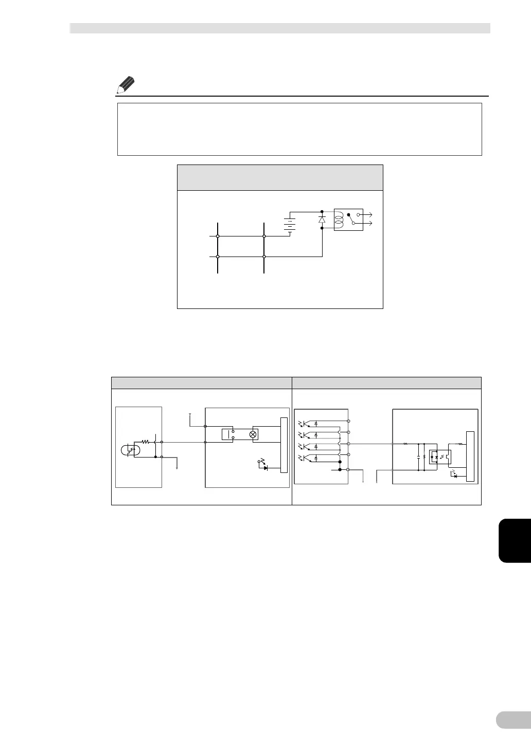
When connecting a device such as a relay that generates counter electromotive force
to the signal output circuit, connect diodes that prevent counter electromotive force to
both ends of the relay.
7-1-7 Example of the use of the Contact Signal circuit
BS signal example of connection with PLC BU signal example of connection with PLC
Example of BU signal output circuit
and the connected circuit
Relay
Connection cable
(Twisted or shielded)
System sideUPS side
BS
COM
0V
24V
4.7kΩ
Internal circuit
Output display LED
[
PLC side
]
OUTPUT UNIT
[
UPS side
]
OUT
Connect the relay output or PNP
type transistor output.
BU
-
COM
0V
24V
IN
[
UPS side
]
Internal circuit
Input display LED
2.4kΩ
+COM
560Ω
1000pF
[
PLC side
]
INPUT
UNIT
Connect the 24 VDC bipolar input
or NPN input.