Chapter 3
3-42
System Design and Installation
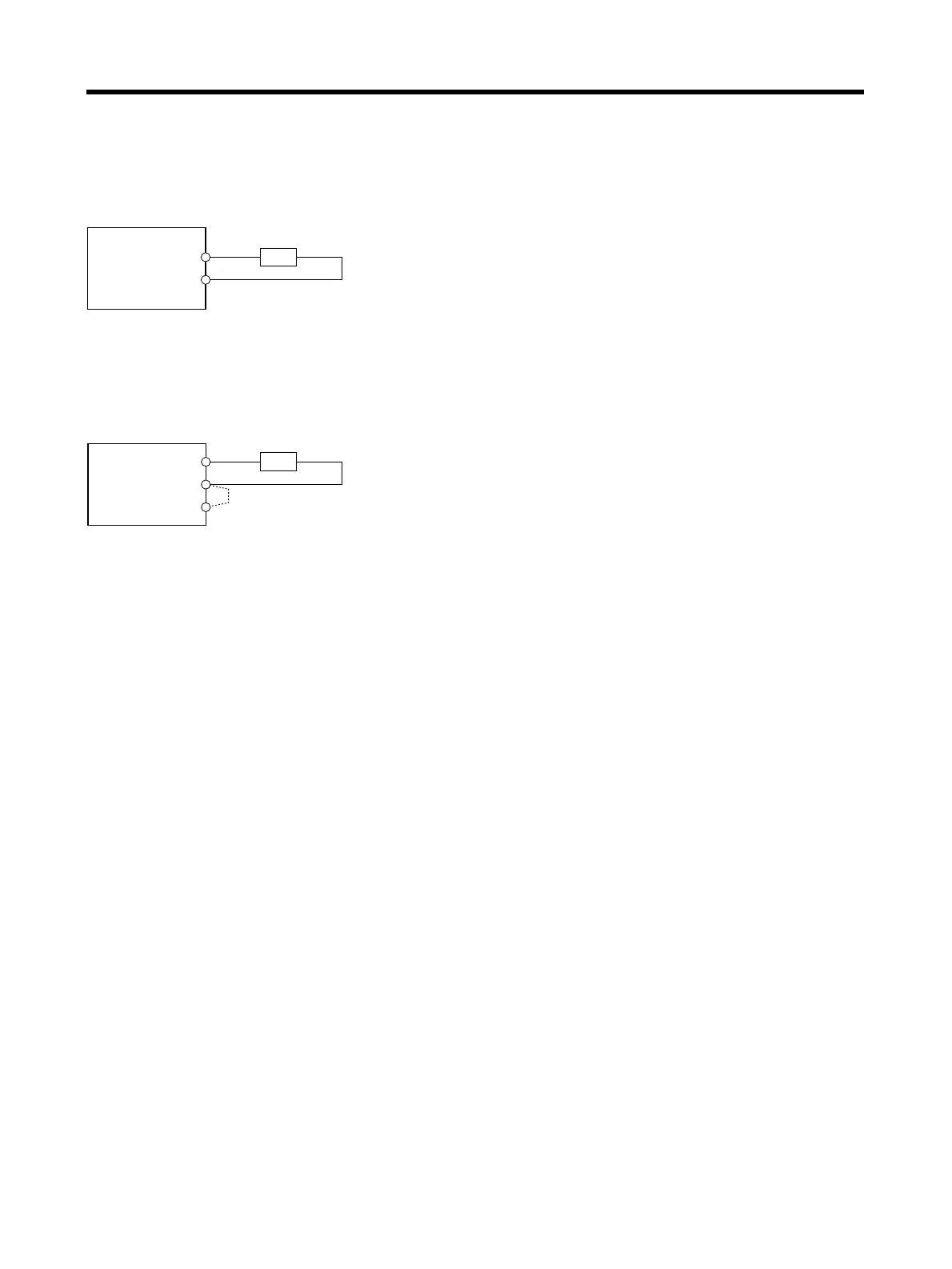
■ Wiring External Regeneration Resistance
● R7D-AP04L and R7D-AP04H
Connect an External Regeneration Resistor between the B1 and B2 terminals.
● R7D-AP08H
Remove the short-circuit wiring between B2 and B2, and then connect an External Regeneration
Resistor between the B1 and B2 terminals.
Servo Driver
External Regeneration Resistor
Note When using the R88A-RR22047S, connect the
thermal switch output so that the power supply will
be shut off when open.
B1
B2
Note 1. The short-circuit wiring between B2 and B3 must be removed.
2. When using the R88A-RR22047S, connect the thermal switch
output so that the power supply will be shut off when open.
← Remove
Servo Driver
External Regeneration Resistor
B1
B2
B3