Chapter 2
2-62
Standard Models and Specifications
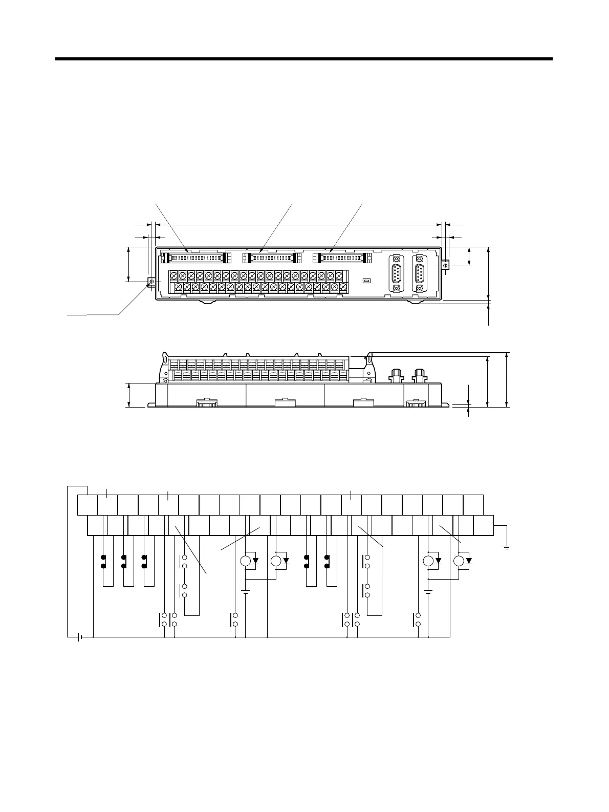
■ XW2B-40J6-4A
This Servo Relay Unit connects to the following OMRON Position Control Units. Communications are
supported.
• CS1W-NC213/-NC233/-NC413/-NC433
• CJ1W-NC213/-NC233/-NC413/-NC433
● External Dimensions
Note Terminal Block pitch: 7.62 mm.
● Wiring
Two, 3.5 dia.
29.5
7
3.5 3.5
7
45
15.5
Y-axis Servo
Driver connector
X-axis Servo
Driver connector
Position Control Unit connector
0
20
19
39
247.5
2.8
20.5
(46)
44.3
2.8
X/Y-axis emergency stop
X-axis
CW
limit
X-axis
CCW
limit
X-axis origin proximity
X-axis
RUN
X-axis
ALM
X-axis
BKIR
Y-axis
CW
limit
Y-axis
CCW
limit
Y-axis origin proximity
Y-axis
RUN
Y-axis
ALM
Y-axis
BKIR
X-axis
external
interrupt
X-axis
RESET
X-axis
ALMCOM
Y-axis
external
interrupt
Y-axis
RESET
Y-axis ALMCOM
Note 1. The XB contact is used to turn ON/OFF the electromagnetic brake.
2. Do not connect unused terminals.
3. The 0 V terminal is internally connected to the common terminals.
4. The following crimp terminal is applicable: R1.25-3 (round with open end).
+24 V
0 V
20
0
39
19
FG
24 V DC
X1 XB
24 V DC
(See note 1.)
Y1 YB
24 V DC
X1 Y1
(See note 1.)
Com-
mon
Com-
mon
Com-
mon
Com-
mon
Com-
mon
Com-
mon
Com-
mon
Com-
mon
Com-
mon
 Loading...


