98
Wiring Section 3-3
• If the I/O wiring and power cables must be placed in the same duct, they
must be shielded from each other using grounded steel sheet metal.
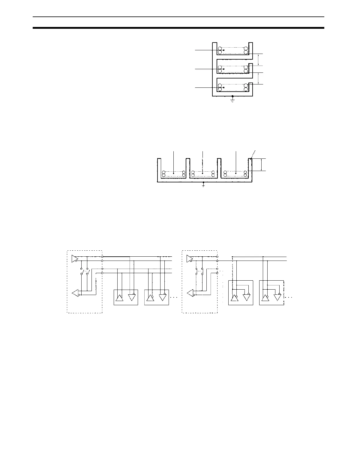
3-3-7 2-Wire and 4-Wire Connections
The transmission circuits for 2-wire and 4-wire connections are different, as
shown in the following diagram.
Note 1. Use the same transmission circuit (2-wire or 4-wire) for all nodes.
2. Do not use 4-wire connections when the 2/4-wire switch on the Board is
set to 2-wire.
3. In protocol macro mode, do not use full-duplex transmissions when the 2/
4-wire switch on the Unit is set to 2-wire. Otherwise, the data sent from the
Serial Communications Board or Unit will be directly returned as receive
data. In this case, the Board or Unit cannot determine whether the data in
the reception buffer is its own send data or the data received from a remote
node, and thus cannot perform receive processing properly. To avoid this
problem, always use half-duplex transmissions with a 2-wire setting. Either
half-duplex or full-duplex transmissions can be used with a 4-wire setting.
Communications
cables
Low-current cables
PLC power supply
and general control
circuit wiring
Power lines
300 mm min.
Ground to 100 Ω or less.
Control cables
Power cables
300 mm min.
Communications
cables
PLC power supply
and general control
circuit wiring
Power lines
200 mm min.
Ground to 100 Ω or less.
Steel sheet metal
Example of 4-Wire
Connections
Example of 2-Wire
Connections
2/4-wire switch
(DPDT)
Board
2/4-wire switch
(DPDT)
Board
Not connected
Other Unit
Other UnitOther Unit
Other Unit