235
Conditions Requiring Routing Tables Section 6-7
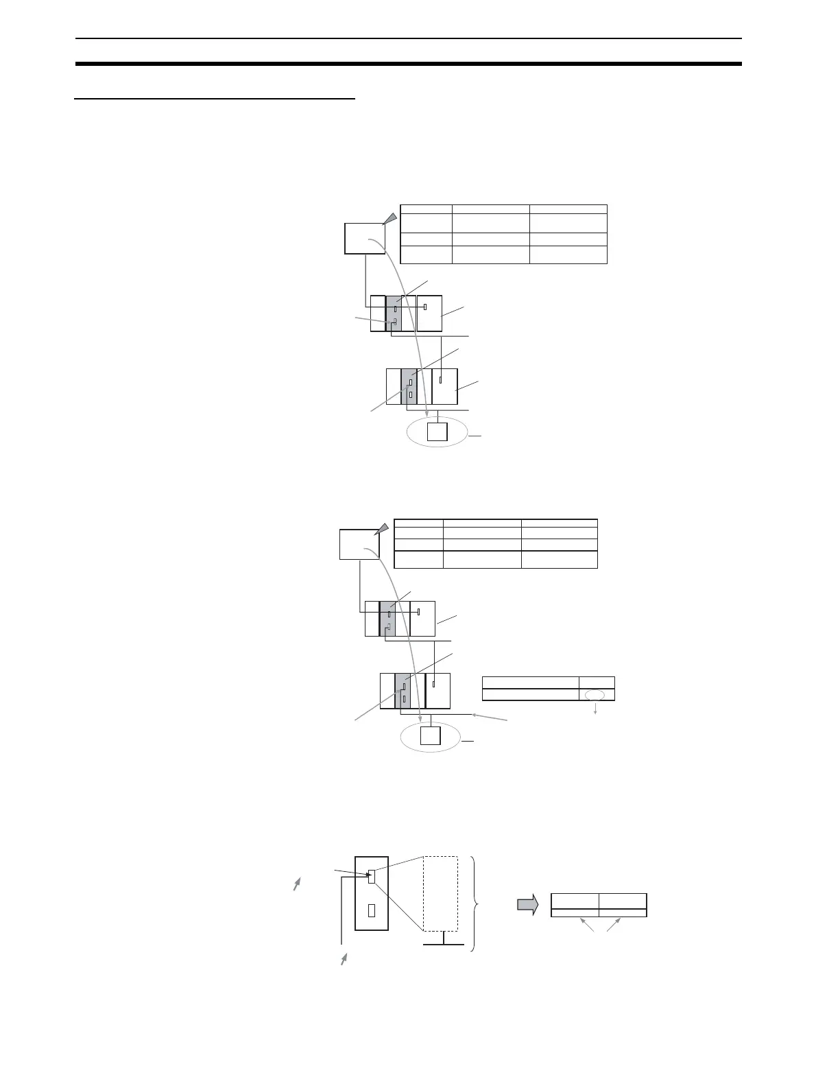
Serial-to-Serial-to-Serial Conversion
Routing tables to enable the serial communications path to be treated as a
network are optional.
Without Routing Tables
Specify the addresses as shown in the following example.
With Routing Tables
Specify the addresses as shown in the following example.
6-7-4 Explanation
To treat the serial communications path as a network, the serial port itself is
recognized as a Communications Unit and is allocated a network address.
Address Specification
Address
Contents
Example
s+1
Serial Communications Unit/Board
E.g., Unit number 2, port 1
Serial Communications Unit/Board
E.g., Unit number 0, port 1
Target: OMRON Component or Modbus Slave
PLC_1
PLC_2
CPU Unit
CPU Unit
FINS
command
sent
Remote net-
work address
Remote node
address
Remote unit
address
PLC_1 serial port
unit address
PLC_2 unit number for
Host Link + 1
PLC_2 serial port
unit address
89 hex (137 decimal)
Calculated from PLC_1 unit
number 2, port 2
80 hex (128 decimal)
Calculated from unit number
0, port 1
Serial communications
path (Host Link FINS)
(1) Network address:
To PLC_1 serial port unit
address (e.g., 89 hex)
No routing tables required to treat serial
communications path as a network
Serial communications
path (Host Link FINS)
No routing tables required to treat serial
communications path as a network
(2) Node address: PLC_2
unit numbers for Host Link
(0 to 31) + 1
(3) Unit address: To
PLC_2 serial port unit
address (e.g., 80 hex)
Serial communications path
(CompoWay/F, Modbus)
Address Contents Example
A
s+1
PLC_2 serial port unit address
Serial Communications Unit/Board
E.g., Unit number 2, port 1
Serial Communications Unit/Board
E.g., Unit number 0, port 1
Target: OMRON Component or Modbus Slave
Unit number
80 hex (128 decimal)
Calculated from unit number 0, port 1
A
CPU Unit
Address Specification
PLC_2
PLC_1
CPU Unit
FINS
command
sent
Serial communications
path (Host Link FINS)
Remote network
address
Remote node
address
Remote unit
address
PLC_2 serial communications
path network address A
PLC_2 unit number for Host
Link + 1
80 hex (128 decimal)
Calculated from unit number
0, port 1
No routing tables required to treat serial
communications path as a network
Routing tables for treating serial
communications path as a network
Serial communications
path (Host Link FINS)
(2) Node address:
PLC_2 unit numbers for
Host Link (0 to 31) + 1
(3) Unit address: To
PLC_2 serial port unit
address (e.g., 80 hex)
Network
address
Serial communica-
tions path (Compo-
Way/F, Modbus)
(1) Network address: To PLC_1 serial
communications path network address A
Serial port
Assigned to network address n
Network
Serial Communications Unit/Board
Local network table in routing tables
Unit number
(See note.)
Set correspondence
Un
Unit address U
(See note.)
Commu-
nications
Unit
Serial communica-
tions path
Ex-
pressed
as:
Network
address
Note: The unit number is set as a
CPU Bus Unit for Communica-
tions Units, but the unit ad-
dress (80 hex/81 hex + unit
number × 4 hex, as a decimal)
is set for the serial
ort.