164
Auxiliary Area and CIO Area Allocations Section 5-3
Software Switch
Descriptions
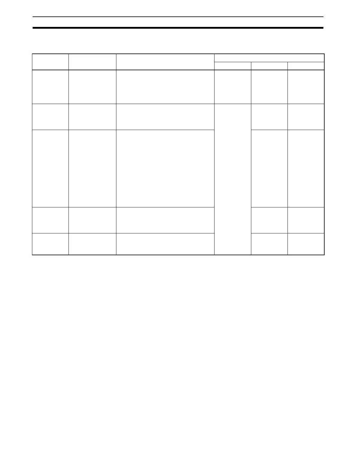
The Software Switches function as described in the following table.
Note 1. The Software Switches will also be initialized at the following times: When
the operating mode is changed between PROGRAM and RUN or MONI-
TOR modes, when STUP(237) is executed, when the Board or Unit is re-
started, or when the communications port is reset.
2. The first switch of the One-shot Trace Switch and Continuous Trace Switch
to turn ON will determine the trace operation. If a Trace Switch turns ON
when a trace operation is already in progress, the switch will not be effec-
tive even when the current trace operation is completed unless the switch
is first turned OFF. If the One-shot Trace Switch and Continuous Trace
Switch turn ON simultaneously, the Continuous Trace Switch will take pri-
ority.
5-3-4 Status Area
The Status Area is used to input status information from Serial Communica-
tions Board or Unit to the CPU Unit. The Status Area is where the Serial Com-
munications Board or Unit set communications status, the transmission
control signal status, and the transmission error status.
Name Bits in CIO 1900
or CIO n
Meaning Timing
Initialize ON OFF
Serial Gate-
way Prohibit
Switch
Bits 04 and 12 The Serial Gateway (mode) is prohib-
ited during protocol macro processing
when this Switch turns ON.
The Serial Gateway is no longer prohib-
ited when the Switch is turned OFF.
Startup Manipulated
by user
Manipulated
by user
Abort Switch Bits 03 and 11 Protocol processing will be aborted
when the switch is turned ON. (Pro-
cessing may be completed if the Switch
is turned ON too late.)
Startup
(Note 1)
Manipulated
by user
Manipulated
by system
One-shot
Trace Switch
(Note 2)
Bits 02 and 10 The CX-Protocol will start a one-shot
trace when the Switch turns ON. The
trace is ended when the Switch is
turned OFF.
The Board or Unit will be cleared when
the trace buffer becomes full.
The CPU Unit will manipulate the One-
shot Trace Switch and Continuous
Trace Switch when trace operations are
performed from the CX-Protocol. Do not
manipulate these switches directly from
a ladder diagram.
Manipulated
by CX-Proto-
col
At end of
one-shot
trace
Continuous
Trace Switch
(Note 2)
Bits 01 and 09 The CX-Protocol will start a continuous
trace when the Switch turns ON. The
trace is ended when the Switch is
turned OFF.
Manipulated
by CX-Proto-
col
Manipulated
by CX-Proto-
col
Wait Release
Switch
Bits 00 and 08
(Not supported by
C200HX/HG/HE)
Standby status for the WAIT command
will be released when the switch is
turned ON.
Manipulated
by user
At end of
WAIT com-
mand