165
Auxiliary Area and CIO Area Allocations Section 5-3
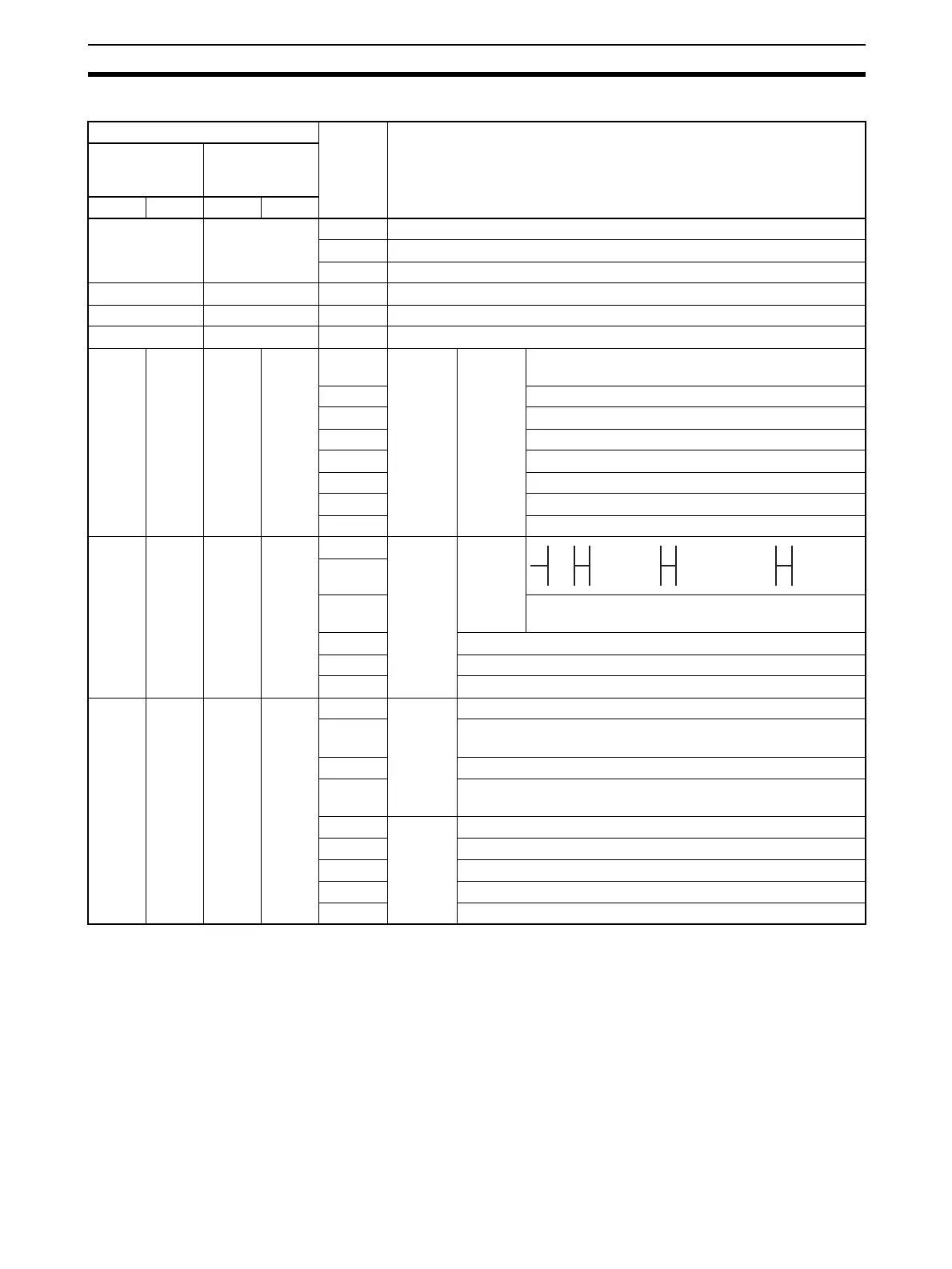
n = CIO 1500 + 25 × unit number
Words Bit Contents
Boards
(CS Series
Only)
Units
(CS/CJ Series)
Port 1Port 2Port 1Port 2
CIO 1901 n + 1 02 to 15 Reserved
01 1: Error log EEPROM error 0: Error log EEPROM normal
00 1: Protocol data error 0: Protocol data normal
CIO 1902 n + 2 00 to 15 Reserved
CIO 1903 n + 3 00 to 15 Reserved
CIO 1904 n + 4 00 to 15 Reserved
CIO
1905
CIO
1915
n + 5 n + 15 12 to 15 Port
setting
status
Setup
settings
Serial communications mode: Always 6 Hex
(see note)
08 to 11 Baud rate (Note 1)
05 to 07 Reserved: Always 0
04 Start bits: Always 1
03 Data length: 7 or 8 bits (Note 1)
02 Stop bits: 1 or 2 bits (Note 1)
01 Parity: Yes/No (Note 1)
00 Parity: Even/Odd (Note 1)
CIO
1906
CIO
1916
n + 6 n + 16 15 Port
setting
status
Hard-
ware set-
tings
(See
note 2)
14
13 0: Terminating resistance OFF
1: Terminating resistance ON
12 to 02 Reserved
01 1: System Setup error; 0: System Setup normal
00 1: Port operating; 0: Port stopped
CIO
1907
CIO
1917
n + 7 n + 17 15 to 11 Commu-
nica-
tions
status
Reserved
10 1: Remote Unit busy receiving (Flow control)
0: Remote Unit ready to receive
09 Reserved
08 1: Local Unit busy receiving (Flow control)
0: Local Unit ready to receive
07 Trans-
mission
control
signal
status
DTR (ER) signal 1: High, 0: Low
06 DSR (DR) signal 1: High, 0: Low
05 Reserved
04 CTS (CS) signal 1: High, 0: Low
03 RTS (RS) signal 1: High, 0: Low
0 No 0 RS-232C 1 RS-422A/485 1 Reserved
0 1 0 1