277
Setup Area Allocations (Modbus-RTU Slave Mode) Section 9-2
9-2-2 Setup Area Contents
m = D30000 + 100 × Unit No.
Port Settings The setting for the port settings determine if the default settings or user set-
tings will be used for port 1 and port 2. Be sure to use the same settings as
the communications port on the host computer connected via the Modbus-
RTU Slave System.
If the default port settings are specified, then the setting of bits 00 and 01 and
the baud rate in D32001 will be ignored.
The default settings used are as follows: Baud rate: 19,200 bps, start bits:
1 bit, data length: 8 bits, parity: even, and stop bits: 1 bit.
If user port settings are specified, set bits 00 and 01 and set the baud rate in
D32001.
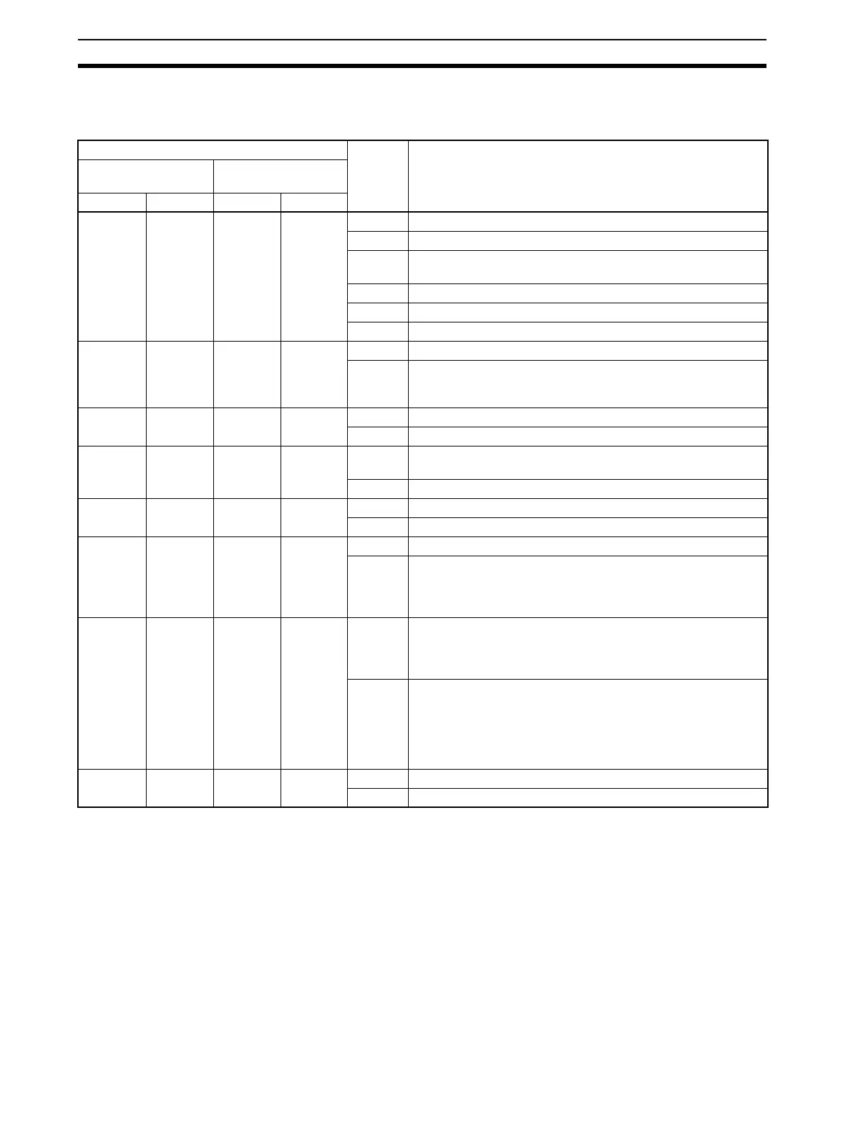
Words Bit Setting contents
Board
(CS Series only)
Unit
(CS/CJ Series)
Port 1 Port 2 Port 1 Port 2
D32000 D32010 m m + 10 15 Port settings 0: Defaults; 1: User settings
12 to 14 Reserved
08 to 11 Serial communications mode
A hex: Modbus-RTU slave
05 to 02 Reserved
01 Parity 0: Yes; 1: No
00 Parity 0: Even; 1: Odd
D32001 D32011 m + 1 m + 11 04 to 15 Reserved
00 to 03 Baud rate (bps)
0: Default (19,200); 3: 1,200; 4: 2,400; 5: 4,800; 6: 9,600;
7: 19,200; 8: 38,400; 9: 57,600; A: 115,200
D32002 to
D32005
D32012 to
D32015
m + 2 to
m + 5
m + 12 to
m + 15
15 Reserved.
14 to 00 Reserved.
D32006 D32016 m + 6 m + 16 15 to 08 Modbus Slave Address
01 to F7 hex (1 to 247)
07 to 00 Reserved.
D32007 to
D32009
D32017 to
D32019
m + 7 to
m + 9
m + 17 to
m + 19
15 to 08 Reserved.
07 to 00 Reserved.
D32020 D32030 m + 20 m + 30 15 to 08 Reserved.
07 to 00 Coils Allocation Area
00 hex: CIO Area
B0 hex: CIO Area, B1 hex: Work Area, B2 hex: Holding Area,
B3 hex: Auxiliary Area
D32021 D32031 m + 21 m + 31 15 to 08 Input Registers Allocation Area
00 hex: CIO Area
B0 hex: CIO Area, B1 hex: Work Area, B2 hex: Holding Area,
B3 hex: Auxiliary Area
07 to 00 Holding Registers Allocation Area
00 hex: DM Area
82 hex: DM Area
50 to 5C hex: EM Area, bank 0 to C
A0 to AC hex: EM Area, bank 0 to C
98 hex: Current bank of EM Area
D32022 to
D32029
D32032 to
D32039
m + 22 to
m + 29
m + 32 to
m + 39
15 to 08 Reserved.
07 to 00 Reserved.