118
RS-232C and RS-422A/485 Wiring Section 3-4
4. Be sure to turn ON the terminating resistance at the last Unit at the end of
the RS-422A/485 cable.
3-4-3 Wiring Connectors
Use the following steps to wire connectors.
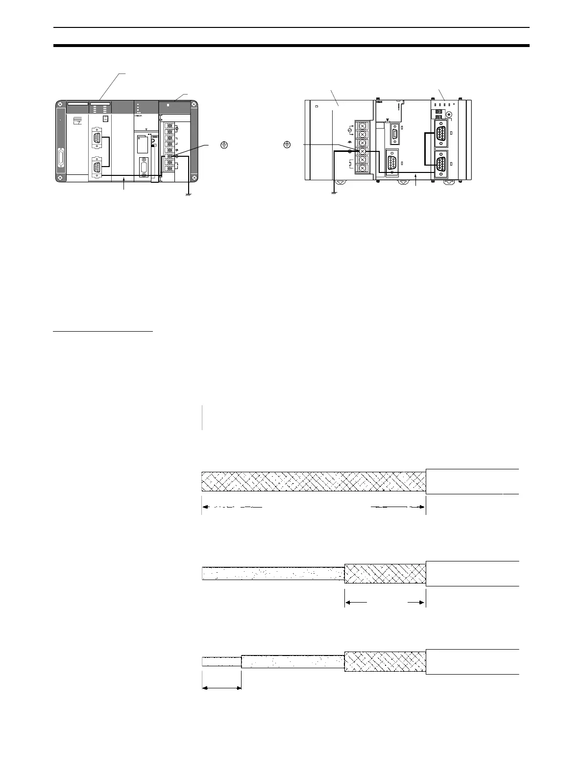
Cable Preparation
See the following diagrams for the length of the cable portion to be cut in each
step.
Shield Connected to Hood (FG)
1,2,3... 1. Cut the cable to the required length.
2. Remove the specified length of the sheath from the cable using a knife. Be
careful not to scratch the braided shield.
3. Trim off the braided shield using scissors so that the remaining shield
length is 10 mm.
4. Remove the insulation from each conductor using a stripper so that the ex-
posed conductor length is 5 mm.
POWER
PA205R
DC24V
AC240V
OUTPUT
RUN
INPUT
AC100-240V
L2/N
L1
CONTROLLER
CJ1G-CPU44
SYSMAC
PROGRAMMABLE
ERR/ALM
RUN
COMM
INH
PRPHL
OPEN
PERIFHERAL
BUSY
MCPWR
PORT
2
ON
4
TERM
ERC
RUN
RD2
SCU41
RD1
TER1
SD2
RDY
NO.
UNIT
ERH
SD1
PORT1
(RS422
/485)
OFF
WIRE
PORT2
0
1
2
3
4
5
6
7
8
9
A
B
C
D
E
F
GR
SYSMAC
CS1G
PROGRAMABLE CONTROLLER
CPU42
OPEN
OPEN
PERIPHERAL
PORT (RS-232C)
BUSY
RUN
ERR/ALM
INH
PRPHL/COMN
MCPWR
GR
POWER
PA204S
L2/N
L1
AC100V-120V/
AC2100-240V/
INPUT
DC24V/0.8A
OUTPUT
100-200
CLOSE
200-240
OPEN
SCU21
PORT1
PORT2
RUN
ERC
SD1
RD1
RDY
ERH
SD2
RD2
E
F
0
1
2
Serial Communications Board/Unit
Power Supply Unit
Hood and GR are
internally connected.
Ground to 100 Ω or less
Grounding the GR terminal
grounds the Hood (FG).
CS-series PLC
CJ-series PLC
Power Supply Unit
Serial
Communications Unit
Hood and GR are
internally
connected.
Grounding the GR
terminal grounds
the Hood (FG).
Ground to
100
Ω or less.
25 mm (RS-422A)
40 mm (RS-232C)
10 mm
5 mm