151
Overview of the Protocol Macro Functions Section 5-1
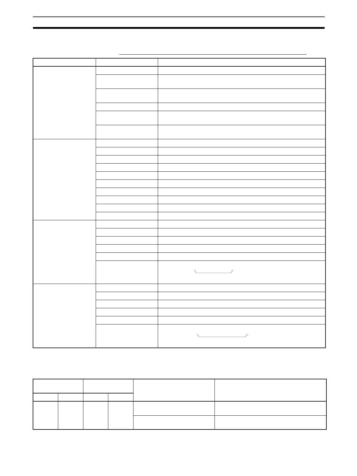
Standard System Protocol Example
Process Value Read Sequence for E5
@K Controller Read Protocol
DM Area Settings for
Standard System Protocol
The following data is set in the Setup Area in the DM Area for a standard sys-
tem protocol.
m = D30000 + 100
× unit number
Level Item Setting
Sequence Link words ---
Transmission control
parameters
Modem control
Response notification
method
Scan
Reception wait time Tr 3 s
Reception finished wait
time Tfr
3 s
Send finished wait time
Tfs
3 s
Steps Step number 00
Repeat counter Reset/001
Command SEND&RECV
Retry count 3
Send wait time ---
Send message SD (00) _1
Receive message RV (00) _1
Response write enable Write
Next process End
Error process Abort
Send message
SD (00) _1
Header <h> “@”
Terminator <t> [2A0D]
Error check code <c> LRC (horizontal parity) (0) (2 bytes of ASCII)
Length <l> ---
Address <a> $ (R (1) ) ,2)
Message edited
Receive message
RV (00) _1
Header <h> “@”
Terminator <t> [2A0D]
Error check code <c> LRC (horizontal parity) (0) (2 bytes of ASCII)
Length <l> ---
Address <a> & (R (1) ) ,2)
Message edited
<h> + <a> + "1" + "00" + "0000" + <c> + <t>
Data
<h> + <a> + "00" + "00" + & (W (1) ,4) + <c> + <t>
Data
Board
(CS Series only)
Unit
(CS/CJ Series)
Contents Setting for a standard system protocol
Port 1Port 2Port 1Port 2
D32000 D32010 m m + 10 Bits 00 to 04: Communications
parameters
Set to match the parameters of the external
device.
Bits 08 to 11: Serial communica-
tions mode
Set to 6 Hex to specify Protocol Macro Mode.