171
Auxiliary Area and CIO Area Allocations Section 5-3
Note When the repeat counter is used to read words and 0 is read, 0 will be stored
and the step will be skipped.
CIO
1911
CIO
1921
n + 11 n + 21 15 to 12 Reserved
11 to 08 Executed Step No. (code)
0 to 15 (0 to F hex)
07 to 04 Reserved
03 to 00 Executed Reception Case No. (code)
0 to 15 (0 to F hex)
CIO
1912
CIO
1922
n + 12 n + 22 15 to 00 Executed Reception Case No. Flag
No. 0 to 15: Correspond to bits 00 to 15
CIO
1913
CIO
1923
n + 13 n + 23 15 to 00 Executed Step No. Flag
No. 0 to 15: Correspond to bits 00 to 15
CIO
1914
CIO
1924
n + 14 n + 24 15 to 08 Repeat Counter Setting Value
1 to 255 (01 to FF hex) (see note)
07 to 00 Repeat Counter Present Value
1 to 255 (01 to FF hex) (see note)
Words Bit Setting contents
Boards
(CS Series Only)
Unit
(CS/CJ Series)
Port 1Port 2Port 1Port 2
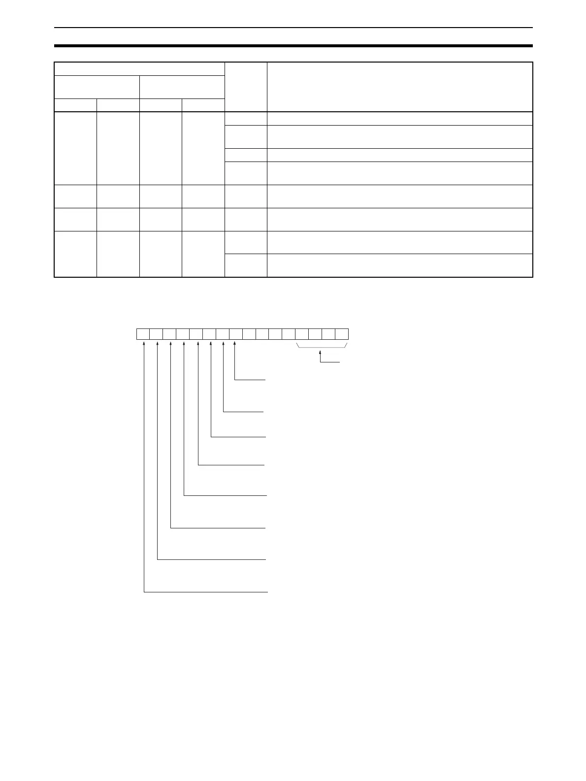
Bit
1: Sequence wait status
0: Other than above
1: Sequence aborted
0: Other than above
1: Trace executing
0: Other than above
1: Protocol macro processing aborted
0: Other than above
1: Step processing error
0: Step processing normal
1: Protocol macro executing
0: Protocol macro executed
1: Sequence ended
0: Other than above
Sequence Wait Flag
Sequence Abort Completion Flag
Sequence End Completion Flag
Tracing Flag
Abort Flag
Step Error Processing Flag
Protocol Macro Executing Flag
CIO 1909 (port 1) or
CIO 1919 (port 2)
n + 9 (port 1) or
n + 19 (port 2)
Error code
00 0 0
15 14 13 12 11 10 09 08 07 06 05 04 03 01 0002
1: Prohibited
0: Not prohibited
Serial Gateway Prohibit Flag
(protocol macro)