482
E5
@
K Digital Controller Read Protocol Appendix F
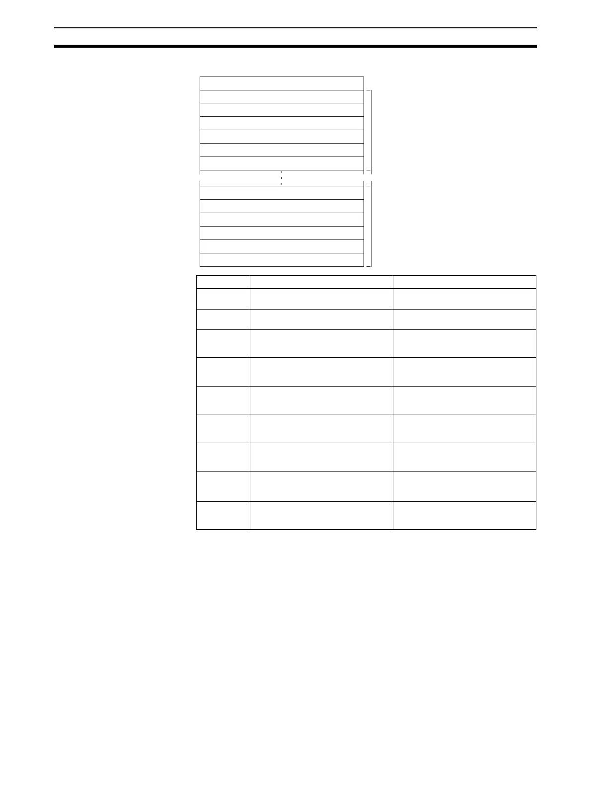
Receive Data Word Allocation (4th Operand of PMCR(260))
Offset Contents (data format) Data
+0 Number of receive data words
(4 digits Hex)
Number of units × 6 + 1
+1 1st unit
Input digital filter (4 digits BCD)
0000 to 9999
+2 1st unit
Alarm 1 hysteresis
(4 digits BCD)
0001 to 9999
+3 1st unit
Alarm 2 hysteresis
(4 digits BCD)
0001 to 9999
+4 1st unit
Alarm 3 hysteresis
(4 digits BCD)
0001 to 9999
+5 1st unit
Input shift upper limit (4 digits BCD)
A999 to 9999
F indicates a negative value and A indi-
cates –1.
+6 1st unit
Input shift lower limit (4 digits BCD)
A999 to 9999
F indicates a negative value and A indi-
cates –1.
•
•
•
+48
(max.)
8th unit
Input shift lower limit (4 digits BCD)
A999 to 9999
F indicates a negative value and A indi-
cates –1.
Input digital filter
Receive data
storage words
Number of receive data words
+0
+1
+2
+3
+4
+5
+6
+43
+44
+45
+46
+47
+48
Input digital filter
Alarm 1 hysteresis
Alarm 2 hysteresis
Alarm 3 hysteresis
Input shift upper limit
~ ~
Alarm 1 hysteresis
Alarm 2 hysteresis
Alarm 3 hysteresis
Input shift upper limit
1st unit
8th unit (max.)
Input shift lower limit
Input shift lower limit