692
V600/V620 ID Controller Protocol Appendix P
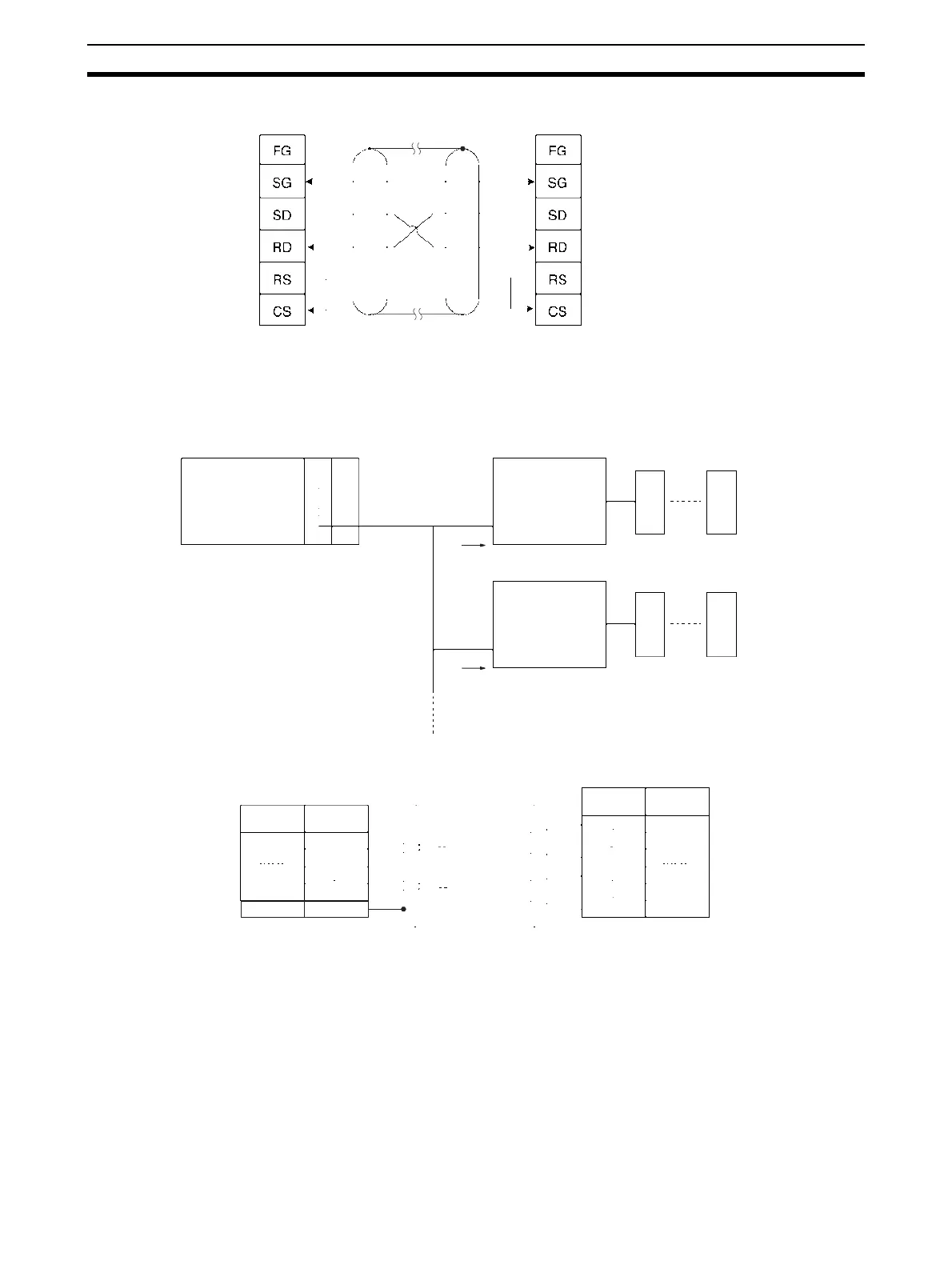
RS-422 Connections
Note 1. Ground the cable shield at either the ID Controller or the Serial Communications Unit/Board to pre-
vent malfunction.
2. Turn ON the pin 6 on DIP switch SW6 to set the host communications procedure to the 1-to-N proce-
dure for 1-to-N connections.
Serial Communications Unit/Board:
D-sub 9 pin (female)
ID Controller (CA1A):
D-sub 25 pin (female)
Shield
U
to 16 units can be connected
RS-422A/485 port
ID Controller
Head Data Carrier
ID Controller
Head Data Carrier
Serial Communications Board
(CS Series only)
Serial Communications Unit
(CS/CJ Series)
PSPLC
RS-422
RS-422
Shield
Signal
name
Pin No.
Signal
name
Pin No.
Serial Communications Board/Unit:
D-sub 9 pin (female)
ID Controller (CD1D):
D-sub 9 pin (female)
FG Hood
1
3
5
6
7
9
RDB
SG
SDB
RDA
FG
SDA
8
2
6
1
RDB
SDB
RDA
SDA