47
Basic Operating Procedure Section 1-9
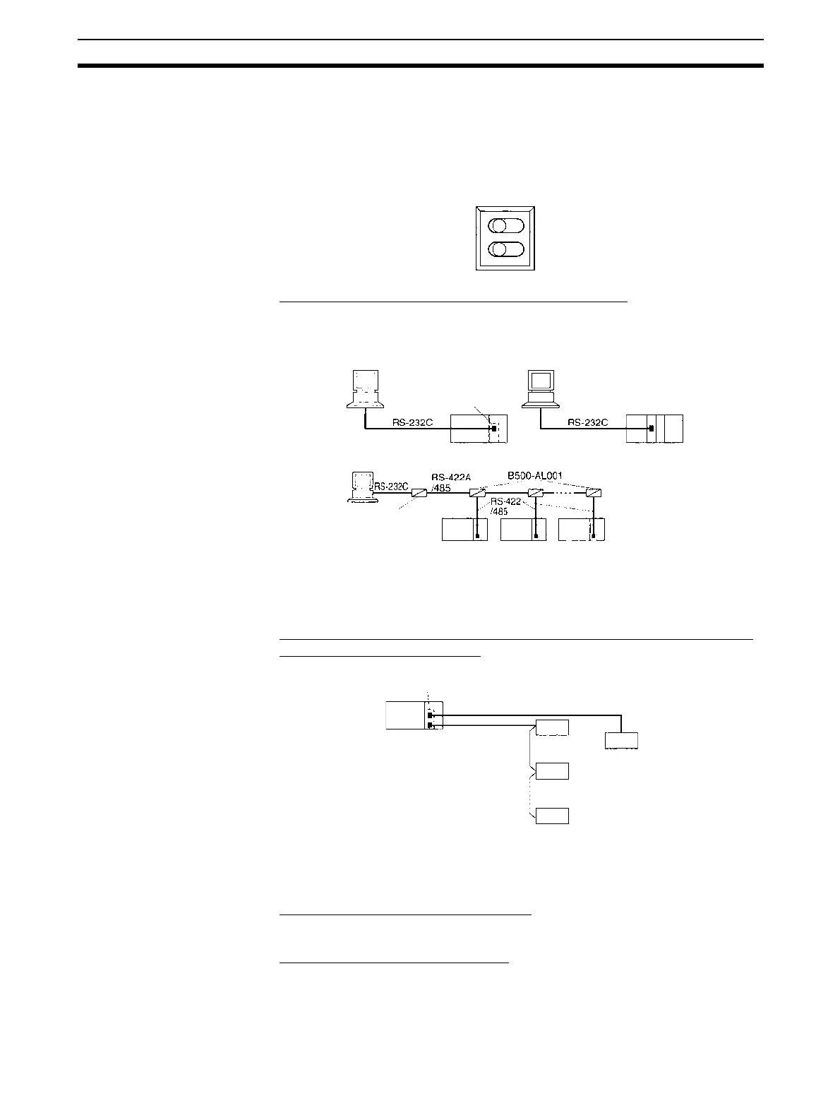
When an RS-422A/485 port is used, the following setting is required.
• TERM: Terminating resistance ON/OFF switch
OFF: Terminating resistance OFF
ON: Terminating resistance ON
• WIRE: 2-wire or 4-wire selector switch
2: 2-wire; 4: 4-wire
Connection Example for Host Link Communications
The host computer can be connected to a PLC 1:1, or NT-AL001-E Convert-
ing Link Adapters can be used to convert from RS-232C to RS-422A/485 to
connect the host computer to PLCs 1:N.
Also perform other required processing, such as setting switches on the exter-
nal device(s).
Connection Example for Protocol Macros, Serial Gateway, No-protocol
Mode, and Modbus-RTU Slave
Also perform other required processing, such as setting switches on the exter-
nal device(s).
Connection Example for 1:N NT Links
Refer to the manual for the PT.
Connecting Programming Devices
Connect the Programming Console, CX-Programmer, or CX-Protocol to the
CPU Unit as required.
Turning ON Power Turn ON the PLC power supply to the PLC.
OFF
2
ON
4
TERM
WIRE
Serial Commu-
nications Board
Serial Commu-
nications Unit
Terminating resistance
ON
NT-AL001-E
Terminating resis-
tance ON, 5-V power
supply required
Serial Communications
Board
Terminating
resistance ON
General-purpose
external device
RS-232C
RS-422A/485
General-purpose
external device
General-purpose
external device
Terminating
resistance ON
General-purpose
external device