Appendix BSpecifications
116
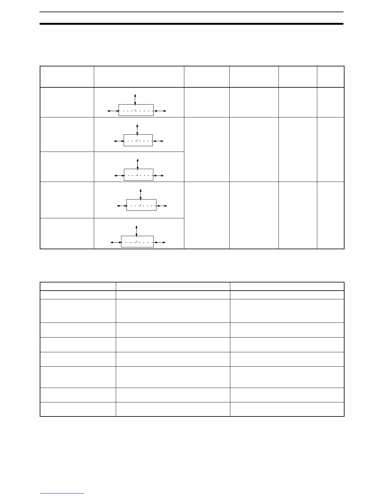
Link Adapters
The following tables gives the specifications for Link Adapters suitable for use In Host Link Systems. Refer to
the Link Adapter Manual for details).
Link Adapter Connection Supply
voltage
Operating
voltage range
Power
consump-
tion
Weight
3G2A9-AL001
RS-422
RS-422RS-422
Not required –––
––– 250 g
max.
3G2A9-AL002-PE
Optical Fiber (APF/PCF)
Optical
Fiber
(APF/
PCF)
Optical
Fiber
(APF/
PCF)
100 to 120/
200 to 240 VAC
or 12 to 24 VAC/
DC
85 to 132/
170 to 246 VAC or
10.2 to 24.6 VAC/
DC
10 VA max. 900 g
max.
3G2A9-AL002-E
Optical Fiber (PCF)
Optical
Fiber
(PCF)
Optical
Fiber
(PCF)
3G2A9-AL004-PE
Optical
Fiber
(APF/
PCF)
RS-232C
RS-422
100 to 120/
200 to 240 VAC
85 to 110 VAC
170 to 220 VAC
10 VA max. 1 kg max.
3G2A9-AL004-E
Optical Fi-
ber (PCF)
RS-232C
RS-422
APF: all-plastic optical fiber cable; PCF: plastic-clad optical fiber cable
Host Link Unit Specifications
Item Port 1 Port 2
Interface RS-232C RS-232C or RS-422 (selectable)
Communications method Half duplex or full duplex; Set in CPU Bus
Unit System Setup.
RS-232C: Half duplex or full duplex; Set in
CPU Bus Unit System Setup.
RS-422: Full duplex
Synchronization method Start-stop, 1 or 2 stop bits; Set in CPU Bus
Unit System Setup.
Start-stop, 1 or 2 stop bits; Set in CPU Bus
Unit System Setup.
Baud rate 1200, 2400, 4800, 9600, or 19200 bps; Set
in CPU Bus Unit System Setup.
1200, 2400, 4800, 9600, or 19200 bps; Set
in CPU Bus Unit System Setup.
Transmitted code 7- or 8-bit ASCII; Set in CPU Bus Unit
System Setup.
7- or 8-bit ASCII; Set in CPU Bus Unit
System Setup.
Error detection Vertical parity, even/odd/none; Set in CPU
Bus Unit System Setup. FCS (frame
checksum sequence)
Vertical parity, even/odd/none; Set in CPU
Bus Unit System Setup. FCS (frame
checksum sequence)
Transmission control Xon/Xoff control; Set in CPU Bus Unit
System Setup.
Xon/Xoff control; Set in CPU Bus Unit
System Setup.
Transmission distance 15 m max. RS-232C: 15 m max.;
RS-422: 500 m total max.