14
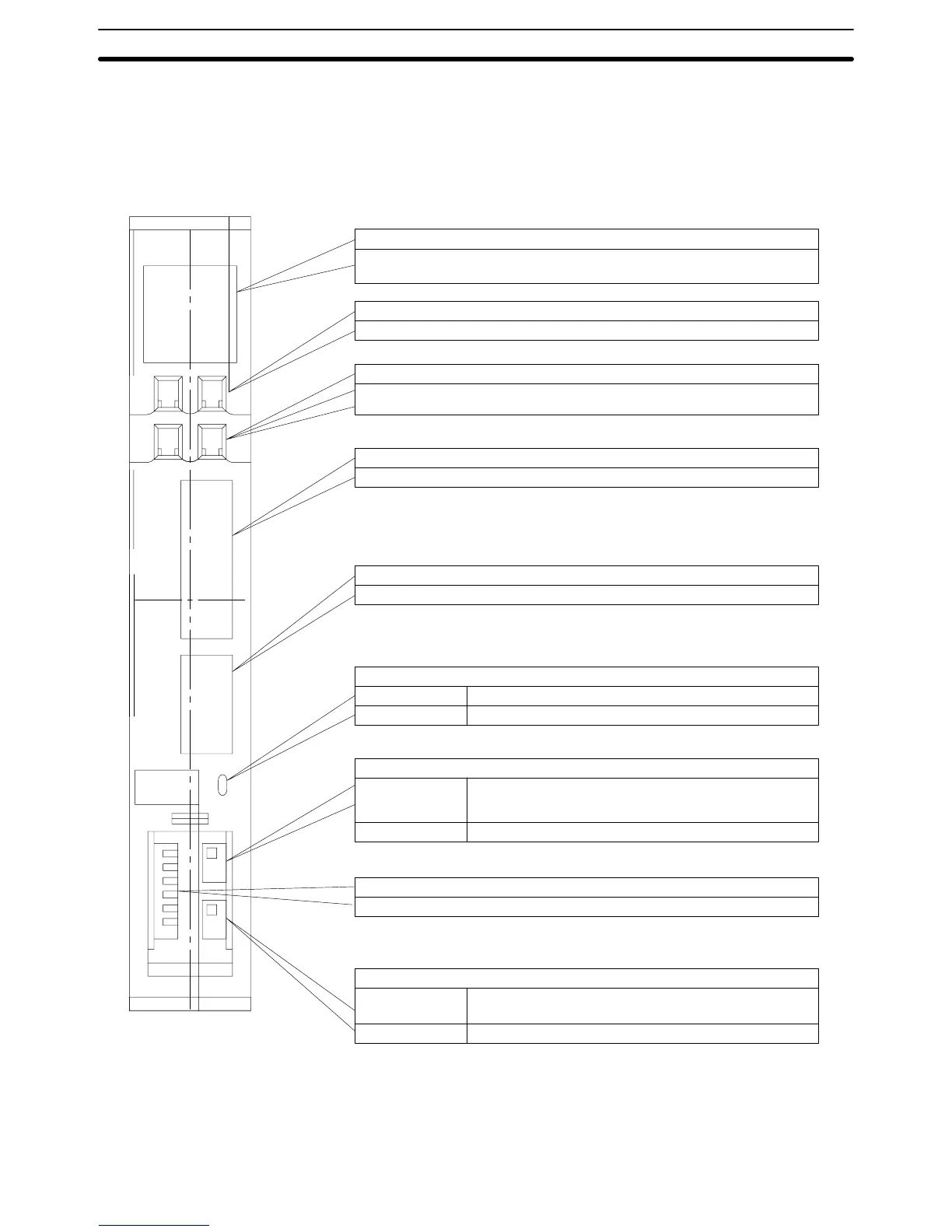
2-2-2 Host Link Unit Components
The following illustration shows the components of the Host Link Unit.
Unit
No.
X10
1
X10
0
X10
1
X10
0
PORT1
RS-232C
PORT2
RS-232C
RS-422
RS-232C
RS-422
Indicators
It is possible to monitor the working condition of the Host Link Unit with these
indicators.
Unit number switch
The unit number is set with this decimal rotary switch.
Node number switch
The node number at communications port 2 is set with this decimal rotary
switch.
Communications port 1 (RS-232C only, 25 pins)
Connects to an RS-232C cable.
Communications port 2 (RS-232C/RS-422 selectable, 9 pins)
Connects to an RS-232C or RS-422 cable.
Communications path selector
Top Selects RS-232C for communications port 2.
Bottom Selects RS-422 for communications port 2.
5-V output switch
Top 5 V, which is used if the optical interface is connected to
communications port 1, is supplied to pin number 14 of
communications port 1.
Bottom 5 V is not supplied to communications port 1.
DIP switch
Basic operations of the Unit are set here.
Terminator switch
Top Connects termination resistance for RS-422
communications.
Bottom Disconnects termination resistance.
Note Cables for the connectors (ports 1 and 2) are not available from OMRON.
Host Link Unit Settings and Parameters Section 2-2