93
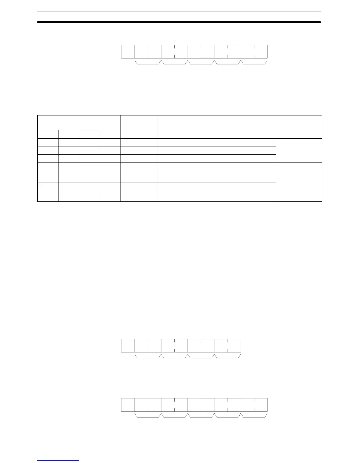
Response Format
@ KR
Unit no. FCS TerminatorHeader
code
Response
code
*s
x 10
0
x 10
1
x 16
1
x 16
0
Parameters Data area, word, bit (command format): Specify in four characters the CIO,
Timer, or Counter Area to be force-reset. Specify in BCD the word (four digits)
and the bit to be force-reset (2 digits).
Data area
Name Word designation Bit
designation
OP1 OP2 OP3 OP4
C I O (S) CIO Area 0000 to 2555 (all CV-series PCs) 00 to 15 (in BCD)
L R (S) (S) Link Area 0000 to 0063 (see note 1) (all CV-series PCs)
H R (S) (S) Holding Area 0000 to 0099 (see note 2) (all CV-series PCs)
T I M (S) Timer Area
(see note 3)
0000 to 0511 (CV500 or CVM1-CPU01-E)
0000 to 1023 (CV1000, CV2000, or
CVM1-CPU11-E)
00 (fixed)
C N T (S) Counter Area
(see note 4)
0000 to 0511 (CV500 or CVM1-CPU01-E)
0000 to 1023 (CV1000, CV2000, or
CVM1-CPU11-E)
(S): Space
Note 1. These correspond to CIO words 1000 to 1063. They do not actually have to
be set as link bits.
2. These correspond to CIO words 1200 to 1299. They do not actually have to
be set as holding bits.
3. The relevant instructions are TIM, TIMH, TTIM, TIMW, and TMHW.
4. The relevant instructions are CNT, CNTR, and CNTW.
5. The space (S) is added because four characters are needed to specify a
data area.
5-27 FORCED SET/RESET CANCEL
Cancels all forced-set and forced-reset bits.
Command Format
@ KC
Unit no. FCS TerminatorHeader
code
*s
x 10
0
x 10
1
Response Format
@ KC
Unit no. FCS TerminatorHeader
code
Response
code
x 10
0
x 10
1
x 16
1
x 16
0
*s
FORCED SET/RESET CANCEL Section 5-27