58
3. The control data set is different from usual control data when commands
(SEND(192), RECV(193), CMND(194) instructions) are sent by the PC.
For program examples that include commands for the host computer, refer to
Appendix D Sample Programs Including Commands for Host Computer.
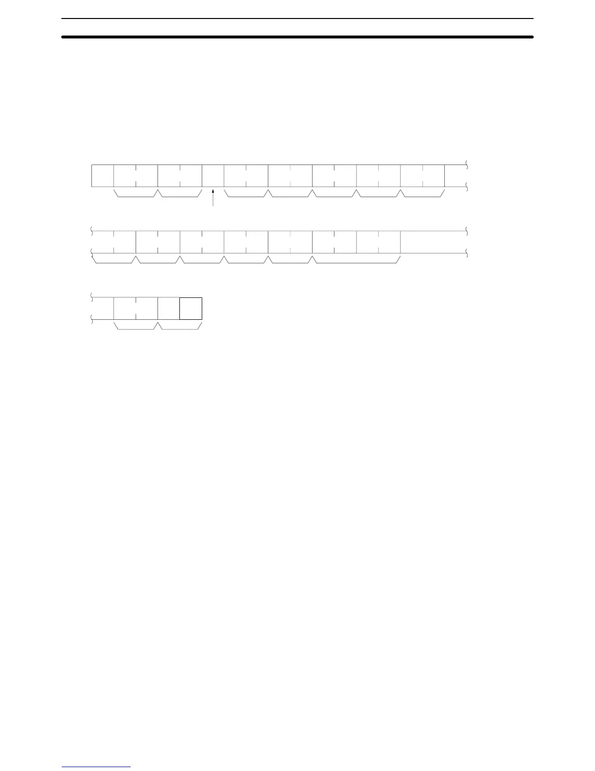
4-4-3 Command Format Received by Host Computers
CV-mode commands addressed to a host computer are received in the following
format by the host computer.
@xxOF08x0x0xxxxx
xxxxxxxxxxxxxx
xx
ICF RSV GCNT DNA DA1
SNA SA1 SA2 SID
FCS
DA2
Node
No.
Header code
Response delay
Command code
Data (1,080 characters max.)
Terminator
*
s
Node Number The block format includes a node number so that the host computer can identify
the Unit that the host computer is communicating with. If the Host Link Unit uses
port 1, 00 (30, 30) must be used. If the Host Link Unit uses port 2, the value set on
the node number setting switches on the front panel of the Host Link Unit must
be designated.
Header Code The header code of the command block format must be set to OF (4F, 46).
Response Delay The response delay must be set to 0 (39) for any FINS command.
ICF Set to 80 (38, 30) if a response from the host computer is required and set to 81
(38, 31) if no response is required.
RSV The port number to which the host computer is connected is set.
Examples:
Communications port 1: 00 (39, 30) or 01 (39, 31)
Communications port 2: 02 (30, 32)
GCNT Subtract the number of relaying networks (SYSMAC LINK or SYSMAC NET)
from 2 and set the resulting value.
Examples:
The number of networks is 0: 02 (30, 32)
The number of networks is 1: 01 (30, 31)
The number of networks is 2: 00 (30, 30)
DNA, DA1, DA2 DNA, DA1, and DA2 specify the Host Link Unit through which the data is sent.
DNA: Set to 00 through 7F to specify the network address of the PC to which the
Host Link Unit is mounted.
DA1: Set to 01 through 7E to specify the node number (unit number) of the PC.
DA2: Set to 10 through 1F to specify the unit address of the Host Link Unit.
SNA, SA1, SA2 SNA, SA1, and SA2 specify the network addresses of the source node.
SNA: Set to 00 through 7F to specify the network address of the source node.
SA1: Set to 01 through 7E to specify the node number of the source node.
SA2: Set to the unit address of the source node.
Sending Commands to Host Computers Section 4-4