39
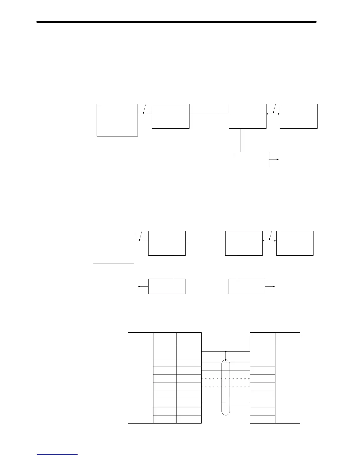
3-7-2 Connections to Optical Module
The connection method of the optical interface varies with the communications
port.
It is possible to connect an Optical Module directly to communications port 1. By
turning on the 5-V power supply switch of the Host Link Unit, 5 V is supplied to pin
14 of the communications port 1 so that no AC Adapter is required for the com-
munications port 1.
Host Link Unit
communications
port 1
Conversion cable
Optical
module
Optical fiber
cable
Optical
module
Direct connection
Host
computer
AC Adapter
Power supply
It is impossible to connect an Optical Module to the 9-pin connector of the Host
Link Unit directly. You must prepare a conversion cable to connect the Optical
Module to the 9-pin connector. AC Adapters are required for the Optical Modules
at the Unit and at the host computer. The following diagram shows the connec-
tions of the Host Link Unit to the host computer via communications port 2.
Host Link Unit
communications
port 2
Conversion cable
Optical
module
Optical fiber
cable
Optical
module
Direct connection
Host
computer
AC Adapter
Power supply
Power supply
AC Adapter
The following diagram shows the connections of the 9-pin to 25-pin conversion
cable.
Signal
name
RS-232C
connector
Pin
number
Host Link Unit
Male connector (9 pins)
Optical Module
Female connector (25 pins)
Pin
number
SD (TXD)
RD (RXD)
RS (RTS)
CS (CTS)
SG (GND)
2
3
4
5
9
FG
3
4
5
6
7
8
20
2
Connector
hood
1
Shield
RS-232C
connector
See note
See note
Communications Port 1
(25-pin connector)
Communications Port 2
(9-pin connector)
Optical Interface Connections Section 3-7