78
Parameters Beginning word (command): Specify in BCD the address of first word to be
written in the Link Area as an offset from CIO 1000. The setting can be between
0000 and 0063.
Data (command): Specify the data to be written in hexadecimal.
Note The boundary of the data area must not be exceeded. For example, if you speci-
fy “0060” for the beginning word and try to write more than four words, an error
will result and no data will be written.
5-12 HOLDING AREA WRITE
Writes data to the specified number of Holding Area words (CIO 1200 to
CIO 1299), starting from the specified offset from the beginning of the area. This
command will be processed properly regardless of whether or not the Holding
Area is actually set for use as holding words.
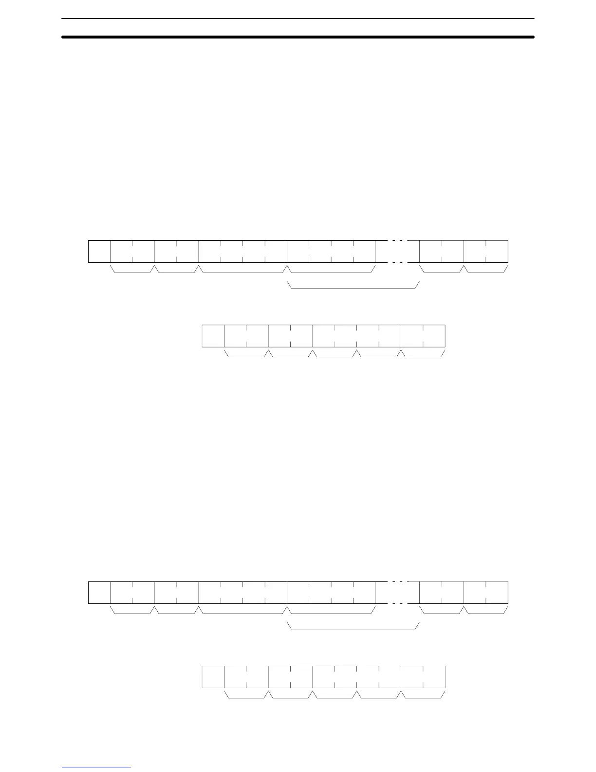
Command Format
@ WH
Unit no. Beginning word FCS TerminatorHeader code Data for beginning word
Data
*s
x 10
0
x 10
1
x 10
3
x 10
2
x 10
1
x 10
0
x 10
3
x 10
2
x 10
1
x 10
0
Response Format
@ WH
Unit no. FCS TerminatorHeader
code
Response
code
*s
x 10
0
x 10
1
x 16
1
x 16
0
Parameters Beginning word (command): Specify in BCD the address of first word to be
written in the Link Area as an offset from CIO 1200. The setting can be between
0000 and 0099.
Data (command): Specify the data to be written in hexadecimal.
Note The boundary of the data area must not be exceeded. For example, if you speci-
fy “0098” for the beginning word and try to write more than two words, an error
will result and no data will be written.
5-13 PV WRITE
Writes PVs (present values) of timers/counters starting from the specified timer/
counter.
Note When data is written, the Completion Flags of the timers/counters will be turned
OFF.
Command Format
@ WC
Unit no. Beginning word FCS TerminatorHeader code Data for beginning word
Data
*s
x 10
0
x 10
1
x 10
3
x 10
2
x 10
1
x 10
0
x 16
3
x 16
2
x 16
1
x 16
0
Response Format
@ WC
Unit no. FCS TerminatorHeader
code
Response
code
*s
x 10
0
x 10
1
x 16
1
x 16
0
PV WRITE Section 5-13