29
Note 1. Ground the FG terminals of both the PC and the host computer to a a resis-
tance of 100 Ω or less. For details refer to the CV-series PC Installation
Guide and your host computer manual.
2. The following Connector and Connector Hood (both OMRON) are provided
with the CPU.
Connector XM2A-0901
Connector hood XM2S-0911
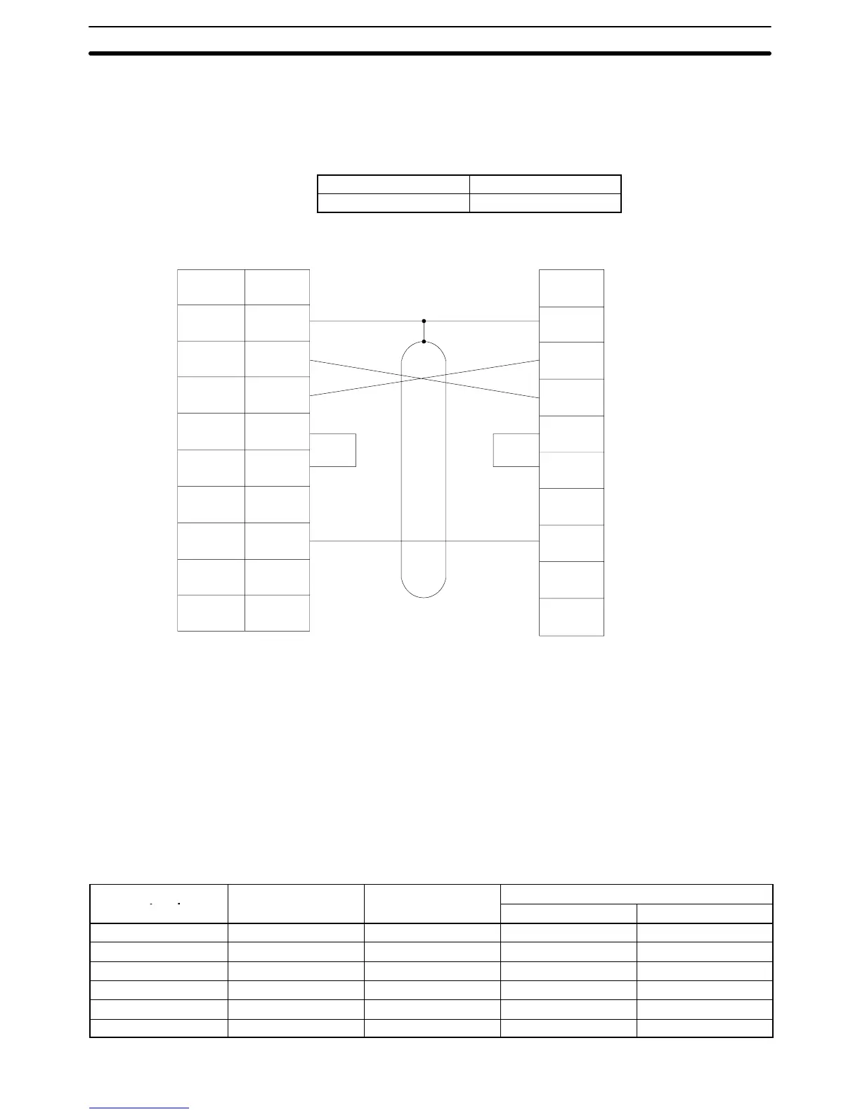
Connection Example The following diagram shows connections between the PC and host computer.
Pin Signal Signal
Host interface (RS-232C) Computer interface (RS-232C)
Shield
9
5
4
3
2
FG
SD (TXD)
RD (RXD)
RS (RTD)
CS (CTS)
SG (GND)
FG
SD
RD
RS
CS
SG
Connec-
tor hood
Note 1. Connect the shield of the cable to the FG (connector hood) of the PC.
2. Pins 1, 6, and 8 on the PC are used when RS-422 is used. Leave them un-
connected when RS-232C is used.
3-4-2 Host Link Unit Connections
The specifications for RS-232C connections to the Host Link Unit are described
in this subsection for ports 1 and 2. When RS-232C cable is used, a host com-
puter can be connected to only one PC.
Communications Port 1 Electrical characteristics: Conforming to EIA RS-232C
Direction of signal: Viewed from the Host Link Unit.
Maximum cable length: 15 m
Host Link Unit
Signal Symbol Direction of signal
connector pin no.
Input Output
Connector hood Frame ground FG --- ---
1 Frame ground FG --- ---
2 Send data SD (TXD) No Yes
3 Receive data RD (RXD) Yes No
4 Request to send RS (RTS) No Yes
5 Clear to send CS (CTS) Yes No
RS-232C Connections Section 3-4