35
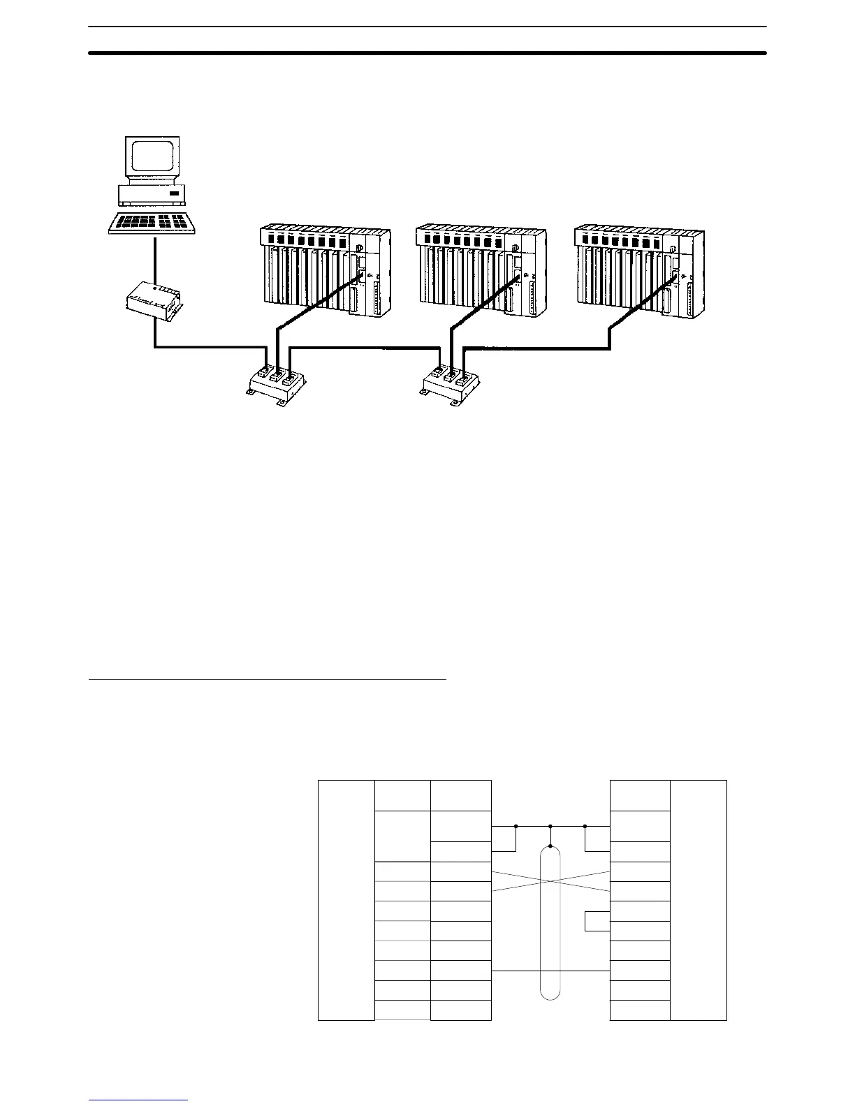
Connecting Shield to FG Connect the frame ground to the shield at the connections to the PCs and at ei-
ther end of the connections between Link Adapters. An example is shown below.
Host computer
3G2A9-AL004-(P)E
Link Adapter
RS-232C
(15 m max.)
3G2A9-AL001
Link Adapter
3G2A9-AL001
Link Adapter
Yes: Connect shield to FG.
No: Do not connect shield to FG.
CV-series PC CV-series PC CV-series PC
RS-422
Yes
No
No
Yes
Yes
Yes
No
No No
Yes
RS-422 RS-422
3-6 1-to-1 Connection Examples
3-6-1 Host Link Unit Connection to Host Computer
The diagrams below show 1-to-1 host link connections between the Host Link
Unit and a host computer via an RS-232C cable.
The wiring method varies with the communications port used and the commu-
nications method (full duplex or half duplex).
Communications via Communications Port 1
The following diagram shows 1-to-1 host link connections using communica-
tions port 1 in full duplex. Full-duplex communication must be set using the Host
Link Unit’s CPU Bus Unit System Setup.
Signal
name
SD (TXD)
RD (RXD)
RS (RTS)
CS (CTS)
SG (GND)
2
3
4
5
7
FG
RS-232C
interface
Pin
number
2
3
4
5
6
7
8
20
RS-232C
interface
1
Pin
number
Host Link Unit Host computer
Connector
hood
Shield
1
Connector
hood
Full Duplex
1-to-1 Connection Examples Section 3-6