79
Parameters Beginning timer/counter (command): Specify in BCD the address of the first
timer to be written to in the Timer Area (0000 through 0511 for the CV500 or
CVM1-CPU01-E and 0000 through 1023 for the CV1000, CV2000, or
CVM1-CPU11-E) or counter to be written to in the Counter Area (2048 through
2559 for the CV500 or CVM1-CPU01-E and 2048 through 3071 for the CV1000,
CV2000, or CVM1-CPU11-E). The area prefix is not required.
Data (command): Specify the PVs to be written in BCD.
Note The boundary of the data area must not be exceeded. For example, if you speci-
fy 510 for the beginning word and try to write more than two PVs for the CV500,
an error will result and no data will be written.
5-14 DM AREA WRITE
Writes data to the DM Area starting from the specified word. The data to be writ-
ten is specified word by word.
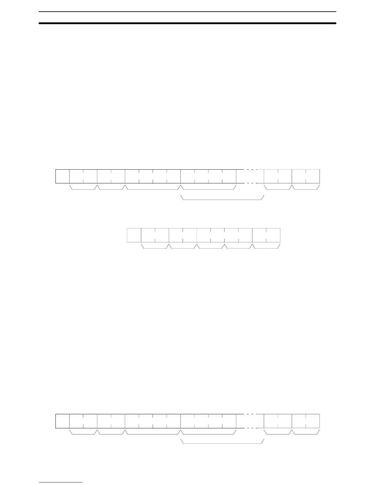
Command Format
@ WD
Unit no. Beginning word FCS TerminatorHeader code Data for beginning word
Data
*s
x 10
0
x 10
1
x 10
3
x 10
2
x 10
1
x 10
0
x 16
3
x 16
2
x 16
1
x 16
0
Response Format
@ WD
Unit no. FCS TerminatorHeader
code
Response
code
*s
x 10
0
x 10
1
x 16
1
x 16
0
Parameters Beginning word (command): Specify in BCD the address of the first word to be
written to in the DM area (0000 through 8191 for the CV500 or CVM1-CPU01-E
and 0000 through 9999 for the CV1000, CV2000, or CVM1-CPU11-E). The area
prefix is not required.
Data (command): Specify the data to be written in hexadecimal.
Note The DM Area in the CV1000, CV2000, or CVM1-CPU11-E runs from D00000
through D24575. In the above command format, however, only the words D0000
through D9999 can be written. To write data to the rest of the DM Area, execute
the MEMORY AREA WRITE CV-mode command (command code: 01 02).
5-15 AUXILIARY AREA WRITE
Writes data to the Auxiliary Area starting from the specified word. The data to be
written is specified word by word.
Note All Auxiliary Area words from A0256 on are read-only.
Command Format
@ WJ
Unit no. Beginning word FCS TerminatorHeader code Data for beginning word
Data
*s
x 10
0
x 10
1
x 10
3
x 10
2
x 10
1
x 10
0
x 16
3
x 16
2
x 16
1
x 16
0
AUXILIARY AREA WRITE Section 5-15