EasyManua.ls Logo

Omron SYSMAC mini SP10 User Manual

Omron SYSMAC mini SP10
176 pages
To Next Page IconTo Next Page
To Previous Page IconTo Previous Page
Page #103 background imageLoading...
Page #103 background image
95
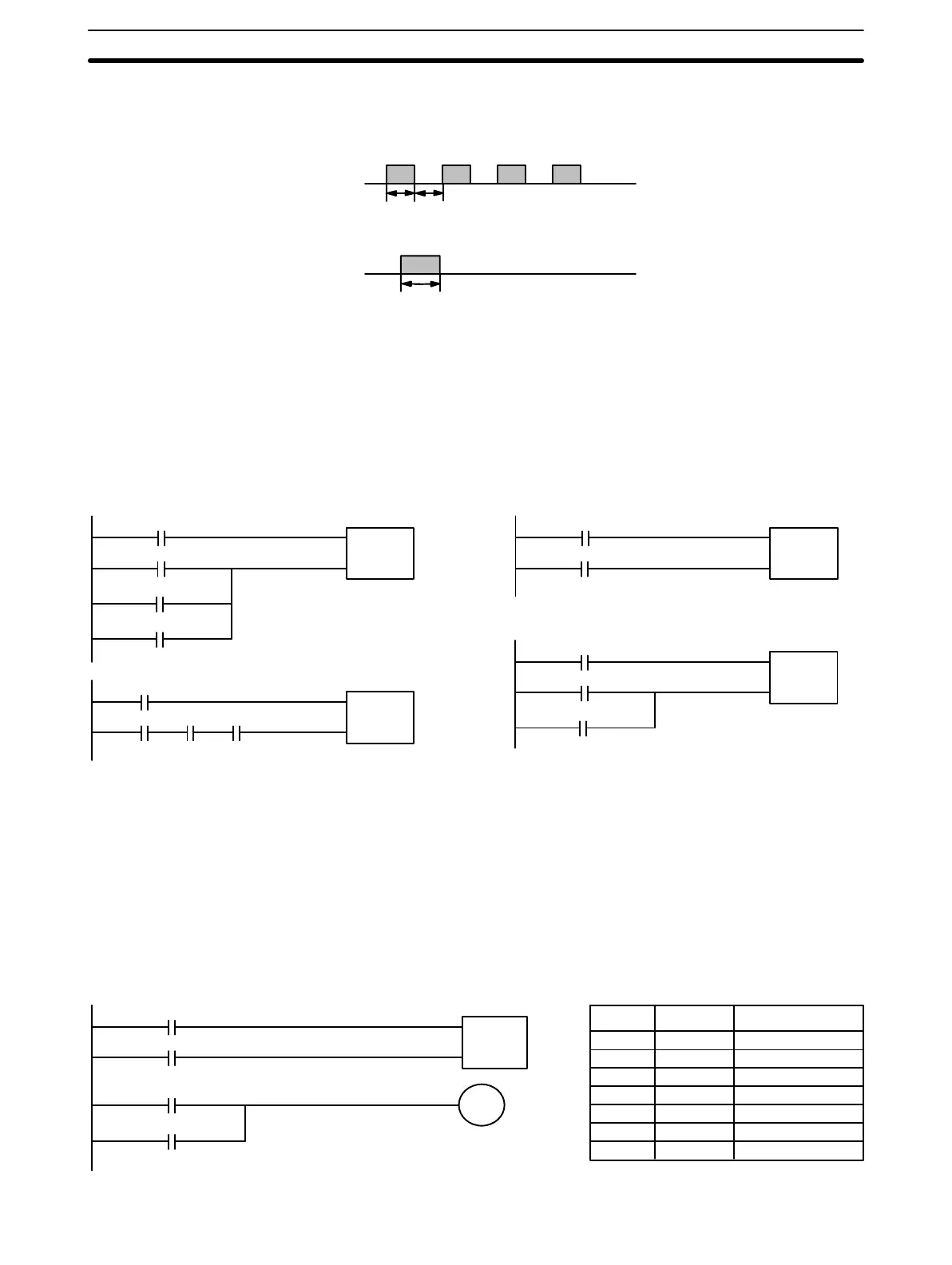
have a duty factor of 1:1, and the reset signal must have an ON time of at
least 250 µs, as shown below.
150
µs
Input
0000
150
µs
250 µs min.
Input
0001
Inputs 0000 and 0001 can be used as normal inputs when CNTH(24) is not
used, but the input signals must be 1 kHz max. (500 µs wide min.).
Do not use the 0001 reset input in combination with other input bits in the
reset execution condition.
0002
SI
R
CNTH(24)
CNT13
#0150
0003
0004
0001
Incorrect
0002
SI
R
CNTH(24)
CNT13
#0150
0001
Correct
0002
SI
R
CNTH(24)
CNT13
#0150
0003
00010004
0002
SI
R
CNTH(24)
CNT13
#0150
0003
0004
Flags ER: The Error Flag (0311) will be turned ON when the SV is not BCD.
The instruction will be executed, but operation will not be reliable.
In the following example, the PV will be incremented whenever the count
pulse, 0000, goes from OFF to ON provided that the start input, 0002, is ON
and the reset input, 2003 is OFF. When 150 pulses have been counted (i.e.,
when the PV reaches the SV), the Completion Flag, CNT 13, and 0101 will
be turned ON.
0002
SI
R
CNTH(24)
CNT13
#0150
2003
0101
CNT 13
Address Instruction Operands
000 LD 0002
001 LD 2003
002 CNTH(24) CNT 13
# 0150
003 LD CNT 13
004 OR 0101
005 OUT 0101
0101
Precautions
Example 1:
Basic Application
Instruction Set Section 3-7

Table of Contents

Question and Answer IconNeed help?

Do you have a question about the Omron SYSMAC mini SP10 and is the answer not in the manual?

Omron SYSMAC mini SP10 Specifications

General IconGeneral
ManufacturerOmron
SeriesSYSMAC mini
ModelSP10
Output TypeRelay
Number of Inputs6
Number of Outputs4
Communication PortRS-232C
TypePLC
Input Voltage100 to 240 VAC
Storage Temperature-25 to 65°C

Summary

PRECAUTIONS

1 Intended Audience

Manual intended for personnel familiar with electrical systems and FA systems.

2 General Precautions

User must operate product per specifications and consult OMRON for non-specified conditions.

3 Safety Precautions

Precautions against electrical shock and electrocution when handling PC.

4 Operating Environment Precautions

Conditions to avoid for proper PC operation, e.g., temperature, humidity.

5 Application Precautions

Precautions for electrical grounding, power supply, and installation.

SECTION 1 Introduction

1-1 Features

Overview of SP-series PCs' compact size, high-performance, and features.

1-2 PC Basics

Explanation of PC components, operation, and terminology.

1-3 Units

Description of CPU, Programming Console, and Link Adapter components.

1-4 PC Configuration

Details on basic and expanded system configurations using PCs and Link Adapters.

SECTION 2 Installation

2-1 Dimensions

Mounting dimensions for CPUs, Link Adapter, and Programming Console.

2-2 Installation

Information on installation environment, cooling, noise prevention, and mounting.

2-3 Wiring

Guidelines for power supply, I/O connections, and wiring precautions.

2-4 Programming Console

Procedures for connecting and designating the PC and input filters.

SECTION 3 Programming

3-1 Introduction

Overview of basic steps for writing, inputting, and debugging programs.

3-2 Memory Areas

Details on memory areas (Input, Output, Work, Dedicated, DR, LR, TC) and their structures.

3-3 The Programming Console

Explanation of Programming Console functions, keyboard, and modes.

3-4 Basic Programming

Core concepts of ladder diagram, terminology, mnemonic code, and basic instructions.

3-5 Inputting the Program

Step-by-step guide for program input, editing, checking, and transfer.

3-6 Advanced Programming

Techniques for interlocks, bit control, differentiated instructions, and work bits.

3-7 Instruction Set

Detailed explanation of all SP-series PC instructions, formats, and execution times.

SECTION 3 Debugging

3-8-1 Displaying and Clearing Error Messages

Procedure to identify, display, and clear error messages using the console.

3-8-2 Reading the Scan Time

Operation to read present and maximum scan times (SP16/SP20 only).

SECTION 3 Program Execution

3-9-1 Scan

Explanation of the CPU scan cycle and its impact on program timing.

3-10 I/O Response Time

Explanation of I/O response time calculation for single PCs and multiple PCs.

SECTION 4 Operation

4-1 Monitoring Operation and Modifying Data

Procedures for monitoring bits, words, timers, counters, and modifying data.

4-2 Memory Card Initialization

Steps to initialize Memory Cards for program backup.

Appendix A Standard Models

Appendix B Specifications

General Ratings

Technical specifications for SP-series PCs, including general ratings.

Input Specifications

Detailed specifications for PC input voltage, impedance, current, and delays.

Output Specifications

Detailed specifications for PC output switching capacity, delays, and life.

CPU Characteristics

Specifications regarding PC control method, I/O control, instruction length, and speed.

Appendix C Programming Instructions and Execution Times

Basic Instructions

Reference for basic ladder diagram instructions, symbols, key inputs, and operands.

Special Instructions

Reference for special instructions like END, Interlocks, STEP, and timers/counters.

Instruction Execution Times

Table detailing instruction execution times based on conditions and operands.

Appendix D Programming Console Operations

Appendix E Error and Arithmetic Flag Operation

Appendix F I/O Assignment Sheets

I/O Bits

Templates for recording I/O bit allocations and terminal assignments for Units.

TC Area and Work Bits

Templates for recording TC area and work bit usage and notes.

Appendix G Program Coding Sheet

Glossary

Index

Revision History

Related product manuals