16
3.2. Installing Wiring for the Load Cell Input Unit
This section shows the examples of wiring to a load cell.
You can connect the Load Cell Input Unit to a load cell with a 6-wire or 4-wire connection. We
recommend that you use a 6-wire connection for connecting the load cell with the Load Cell
Input Unit to achieve high-precision measurements.
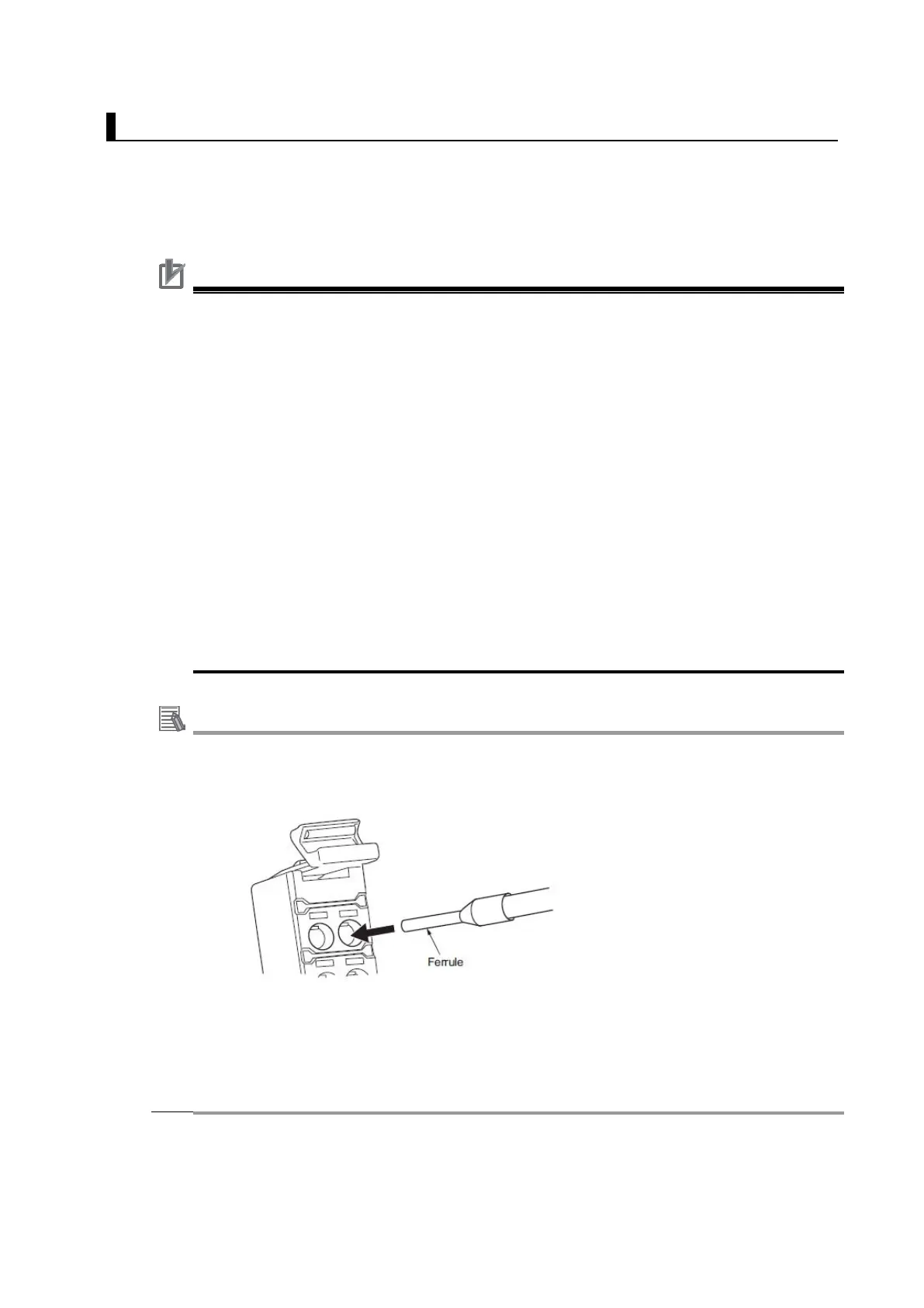
The Load Cell Input Unit uses screwless clamping terminal blocks. The use of
ferrules makes wiring an easy matter of inserting them. The screwless design greatly
reduces wiring work.
The sensor disconnection test is available for the Load Cell Input Unit. Using the
sensor disconnection test after the completion of wiring allows you to check whether
there is a cable disconnection and a non-connected wiring. Refer to the NX-series
Load Cell Input User’s Manual (Cat. No. W565) for details on the sensor
disconnection test.
Precautions for Correct Use
Use a shielded cable to connect to the load cell. Connect the shield wire to the SHLD
terminal on the Load Cell Input Unit.
Ground the functional ground terminal on the Load Cell Input Unit to 100 Ω or less.
We recommend that you use a 6-
wire connection for connecting the load cell with the
Load Cell Input Unit to achieve high-precision measurements. When you use a 4-
connection, the measurement resolution of wiring resistance decreases due to
temperature changes.
Keep the wiring resistance from the load cell to the Load Cell Input Unit to 5 Ω or less
while in use.
Wire the cable that connects the load cell and the Load Cell Input Unit separately from
AC power supply lines or power lines in
order to avoid the effects of the noise. Do not
place such lines in the same duct.
Insert a noise filter into the power supply input section if noise may overlap from
power supply lines when using the same power supply to power an electrical welder
or an electric discharge machine, or there is a high-frequency source nearby.

 Loading...


