18
3.2.3. Wiring Example of Parallel Connection
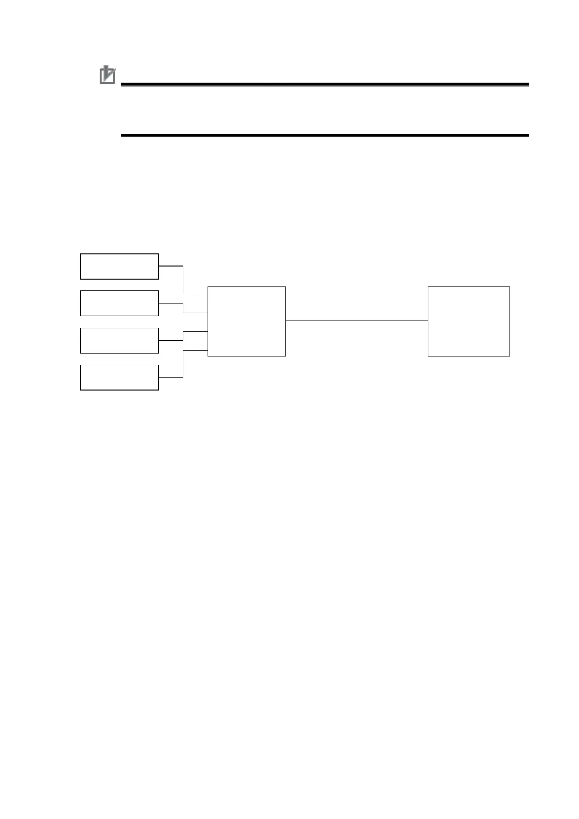
The system configuration example in this Guide is based on the assumption that one load cell is in
use, but multiple load cells can be connected in parallel by using a summing box as in the diagram
below. Refer to 4-4 Wiring the Connected External Devices described in the NX-series Load Cell
Input Unit User’s Manual (Cat. No. W565).
Shielded cable
6-wire connection
Precautions for Correct Use
When you use the Load Cell Input Unit with a 4-wire connection, always connect S+
terminal with EXC+ terminal, and S- terminal with EXC- terminal on the terminal block. If
they are not connected, the Load Cell Input Unit does not operate normally.

 Loading...


