Examples and tips
PROGRAMMING MANUAL 274
Revision 1.0
The inputs in the table above are located on the CN1 I/O connector of the
respective Servo Driver. The pin arrangement of this connector is different
for the respective Servo Drivers. For the Sigma-II and Sigma-V Servo
Drivers, the input signals P_OT, N_OT, DEC, EXT1, EXT2, EXT3, BRK,
IO12, IO13, IO14 and IO15 can be mapped to pins of the CN1 I/O
connector. To do this, you must set the appropriate parameter of the Servo
Driver. The table below shows the possible settings and parameter values.
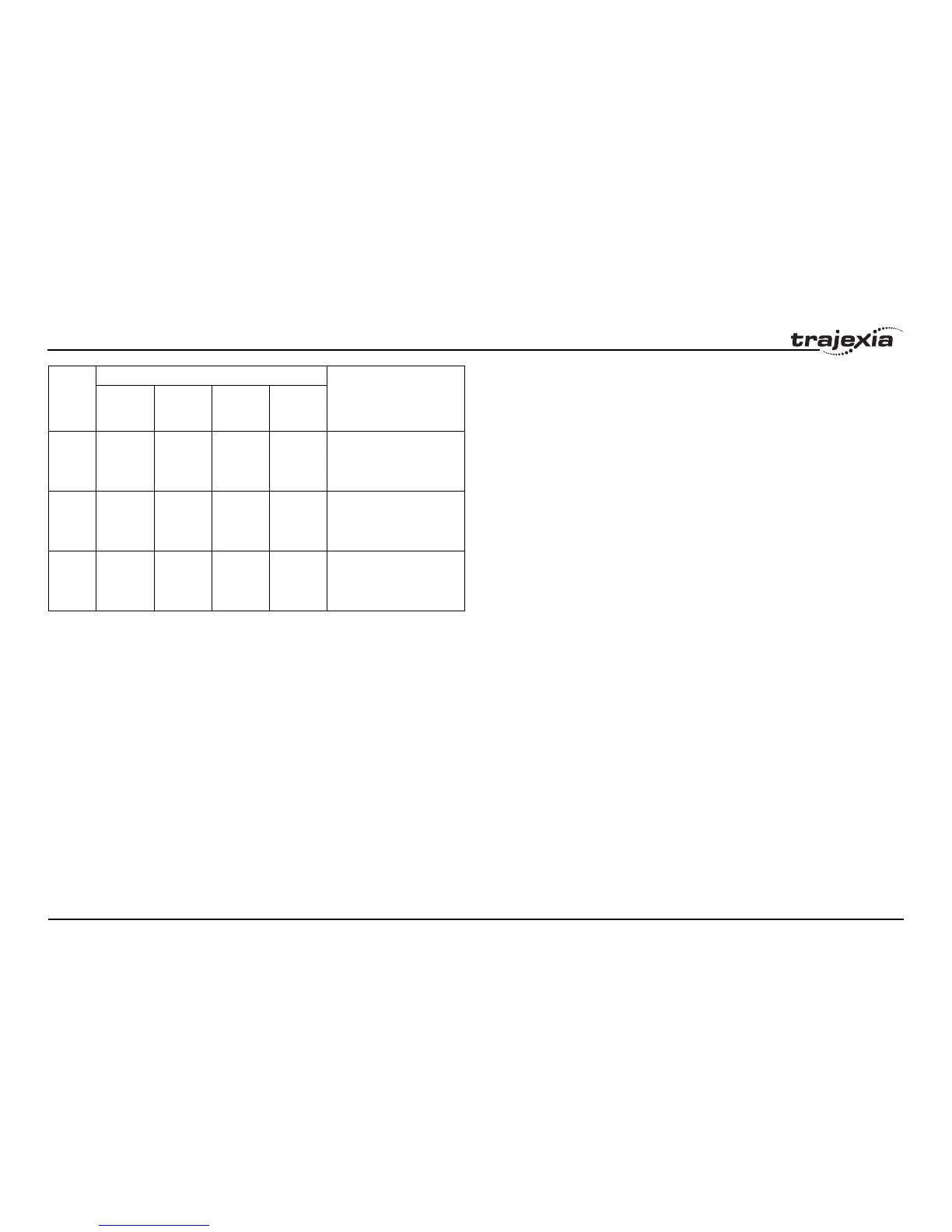
29 IO13 IO13 Not used NCL General input 13 (Sigma-II
and Sigma-V), Torque limit
input in negative direction
(G-Series and Accurax G5)
30 IO14 IO14 Not used SI0 General input 14 (Sigma-II
and Sigma-V), General input
0 (G-Series and Accurax
G5)
31 IO15 IO15 Not used SI1 General input 15 (Sigma-II
and Sigma-V), General input
1 (G-Series and Accurax
G5)
Trajexia
input
Servo Driver input signal Description
Sigma-II Sigma-V Junma G-Series
Accurax
G5